LINK Systems OmniLink - Feed Interface User Manual
Page 10
OmniLink 5000 Feed Manual
December 13, 1999
2.4
Manual Rev 2.3
2.5
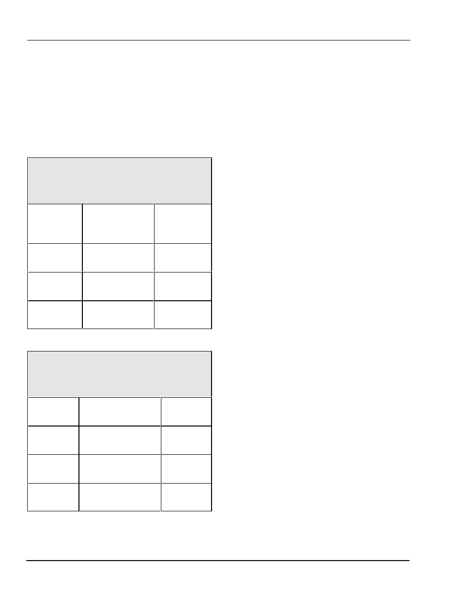
Coe ServoMaster Interface
The connection to a Coe ServoMaster Feed uses
two cables - an adapter cable to go from a telephone
type connector on the operator interface of the
ServoMaster to a DB-9 connector, and a longer
cable to go from the DB-9 connector to the Link
operator terminal.
Table 2.3
Coe ServoMaster Connections
(Adapter Cable) Link PN 107921
DB-9
Female
Function
Coe
Telephone
Jack
Pin 1
(GND)
Ground
Pins 3 and 4
Pin 2
(RXD)
Transmit data to
feed
Pin 5
Pin 3
(TXD)
Receive data
from feed
Pin 2
Table 2.4
Coe ServoMaster Connections
(Main Cable) Link PN 105721
OmniLink
Feed Port
Function / Color
DB-9
Male
Pin 1
(GND)
Ground (WHITE)
Pin 5
Pin 2
(RXD)
Receive data from
feed (BLACK)
Pin 3
Pin 3
(TXD)
Transmit data to
feed (RED)
Pin 2
Notes:
The telephone jack is located on the back of the
Coe operator interface terminal
The feed communications settings (as set in the
Coe operator terminal) should be 9600 Baud, 7
data bits, Odd parity, 1 stop bit.