Neuron 3150 control module keepout areas, D neuron 3150 control module keepout areas – Echelon LonWorks Twisted Pair Control Module User Manual
Page 39
LonWorks Twisted Pair Control Module User's Guide
31
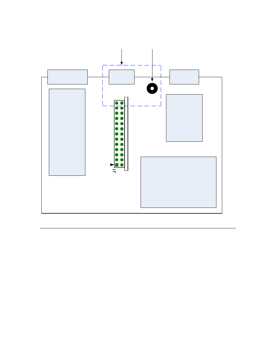
FT 5000 Control Module
Network
Connector
Host Microprocessor
(Optional)
Power Supply
Circuitry
I/O Circuitry
I/O
Connectors
Power Supply
Connector
Center
of Star
Ground
EMC
Keepout
Area
Figure 15. Example PCB Layout Design for an FT 5000 Control Module
Neuron 3150 Control Module Keepout Areas
Figure 16 on page 32 shows three “keepout” areas on the Neuron 3150 Control
Modules. Area #1, the “EMI Radiated Keepout Area,” covers the Neuron Chip
and the PROM. This is the area of the control module that generates the most
RF noise. Cables, long metal chassis parts, and drive circuits for external cables
must be kept away from this part of the control module.
Area #2, the “EMI Susceptibility Area,” is the main twisted pair transceiver area
on the control module, and any RF energy that couples into this part of the
module circuit will be conducted out onto the network cable. High frequency and
high-speed circuits should be kept well away from this area of the control module
(and away from the network connector).