Reset pin, Table 4, D table 5 – Echelon LonWorks Twisted Pair Control Module User Manual
Page 13
LonWorks Twisted Pair Control Module User's Guide
5
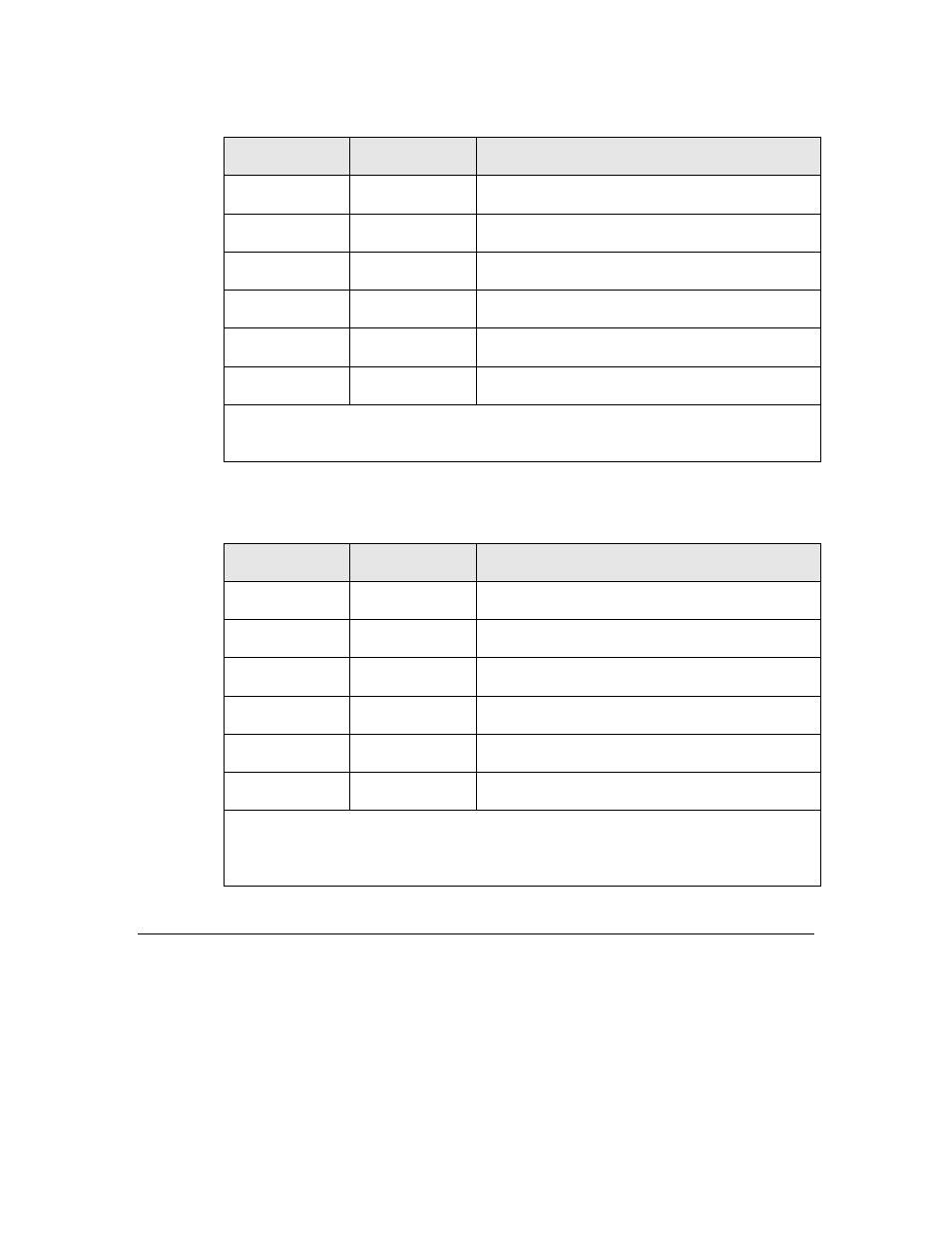
Table 4. 6-pin Network Connector (P2) for the TP/XF Control Modules
Pin Number
Name
Description
1
CTB
Transformer center tap
2
CTA
Transformer center tap
3
Data B
Network data B signal
4
Data A
Network data A signal
5
NC
No connection
6
NC
No connection
Note: CTA and CTB must be shorted together on the applications electronics
board.
Table 5. 6-pin Network Connector (P2) for the TP/FT-10 and TP/FT-10F
Control Modules
Pin Number
Name
Description
1
1
No connection
2
2
No connection
3
Data B
Network data B signal
4
Data A
Network data A signal
5
5
No connection
6
6
No connection
Note: The TP/FT-10 and TP/FT-10F Control Modules incorporate DC blocking
capacitors and therefore can directly connect to either non-link power or link
power channels.
Reset Pin
Pin 2 of the JP1 header on the FT 5000 Control Module is the Smart Transceiver
reset pin (RST~). Pin 9 of the P1 header on the Neuron 3150 Control Module is
the Neuron Chip reset pin (RESET~).
The reset pin on the Smart Transceiver or Neuron Chip can be driven low
externally or can be used as an open drain output to provide a reset signal for the
application circuit. The details of the recommended circuit and loading on the