P1 and p2 connector terminals – Echelon LonWorks Twisted Pair Control Module User Manual
Page 12
4
Electrical Interface
P1 and P2 Connector Terminals
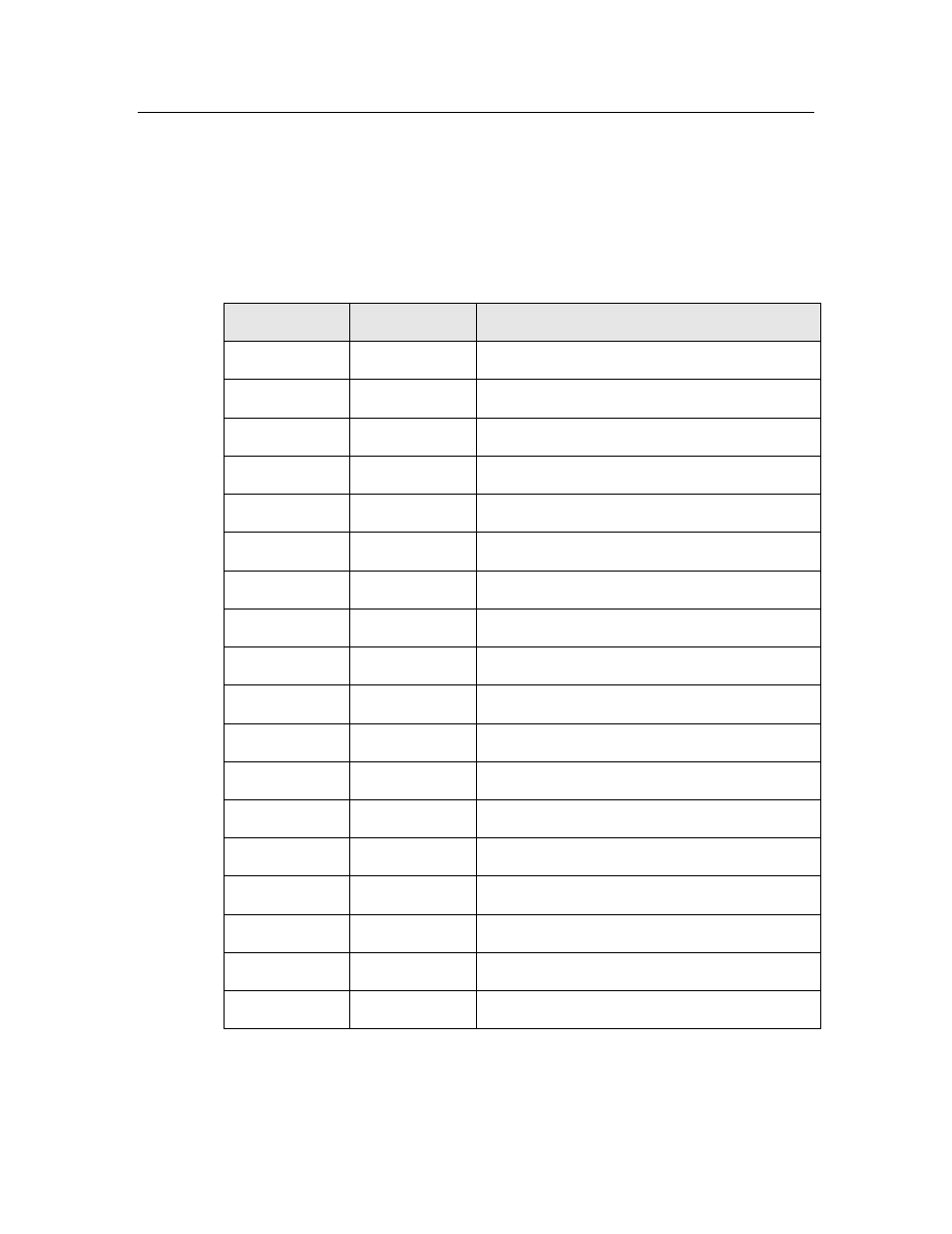
Table 3, Table 4 on page 5, and Table 5 on page 5 show the pinout of the P1
and P2 connector terminals for the Neuron 3150 Control Modules. The I/O pin
function names defined in Table 3 are the same as those used in the Neuron
Chip Data Book, which defines the functions and electrical characteristics for the
signal names. The I/O signals are connected directly to the Neuron 3150 Chip
without buffering.
Table 3. 18-pin I/O Connector (P1) for Neuron 3150 Control Modules
Pin Number
Name
Description
1
NC
No Connect
2
IO0
IO0 for I/O objects
3
GND
Ground
4
IO1
IO1 for I/O objects
5
GND
Ground
6
IO2
IO2 for I/O objects
7
GND
Ground
8
IO3
IO3 for I/O objects
9
RESET~
Reset (active low)
10
IO4
IO4 for I/O objects
11
IO5
IO5 for I/O objects
12
+5 V
5 V Input Power
13
IO6
IO6 for I/O objects
14
IO9
IO9 for I/O objects
15
IO7
IO7 for I/O objects
16
IO10
IO10 for I/O objects
17
IO8
IO8 for I/O objects
18
SERVICE~
Service (active low)