Ft 5000 control module, Jp1 connector – Echelon LonWorks Twisted Pair Control Module User Manual
Page 10
2
Electrical Interface
FT 5000 Control Module
The following sections describe the electrical interface for the FT 5000 Control
Module.
JP1 Connector
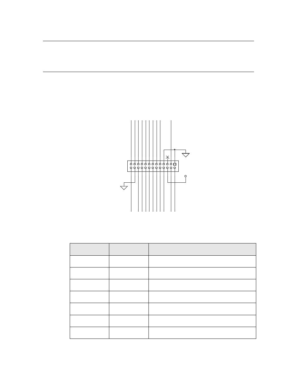
Figure 1 and Table 2 show the pinout of the JP1 header connector for the FT
5000 Control Module. The I/O pin function names defined in Table 2 are the
same as those used in the Series 5000 Chip Data Book, which defines the
functions and electrical characteristics for the signals. The I/O signals are
connected directly to the FT 5000 Smart Transceiver without buffering.
M
OV_GN
D
IO2 IO0
C
P
2_
T
X
LE
D
SVC
-
RS
T-
FT_
NE
TA
IO
10
IO8 IO6 IO4
SC
L
SD
A_C
S1-
IO
11
FT_
NE
TB
IO3 IO1
IO5
IO9 IO7
VDD3V3
C
P
3_
R
X
LE
D
JP1
HEADER 13X2
2
4
6
8
10
12
14
16
18
20
22
24
26
1
3
5
7
9
11
13
15
17
19
21
23
25
Figure 1. FT 5000 Control Module JP1 Connector
Table 2. FT 5000 Control Module JP1 Connector
Pin Number
Signal Name Description
1
GND
Ground
2
RST~
Reset (active low)
3
CP3_RXLED
RxActive for network activity LED
4
CP2_TXLED
TxActive for network activity LED
5
NC
No Connect
6
VDD3V3
3.3 V Input Power
7
GND
Ground