Ft 5000 control module, Floorplan layout, Mechanical footprint – Echelon LonWorks Twisted Pair Control Module User Manual
Page 16: Neuron 3150 control module
8
Mechanical Considerations
FT 5000 Control Module
The following sections describe the mechanical interface for the FT 5000 Control
Module.
Floorplan Layout
Figure 3 shows three views of the floorplan layout of the FT 5000 Control
Module with some of its prominent features labeled.
FT-X3
1
1
2
3
4
8
7
6
5
FT
5000
AT
24C
512
Y1
1
RV1
C7,17
43.18 mm
(1.7 in)
29.85 mm
(1.175 in)
Back View
Front View
Side
View
16 mm
(0.63 in)
Figure 3. FT 5000 Control Module Floorplan Layout
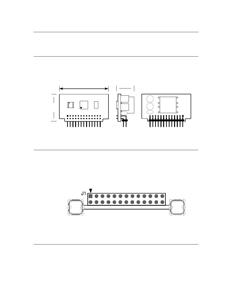
Mechanical Footprint
Figure 4 shows the mechanical footprint for an FT 5000 Control Module. You
can solder the module directly to your PCB as a through-hole part or mount it in
a connector. The module includes a male Samtec, Inc. TSW-113-08-T-D-RA
square post header, which fits into a 13x2 pin female connector, such as a
Samtec, Inc. SSM-113-L-DV surface mount socket strip.
Figure 4. FT 5000 Control Module Mechanical Footprint
The figure also shows positioning for Richco
®
Inc. VMCGE-30M-01 vertical
mount card guides for the Control Module. The card guides are optional,
depending on your application.
Neuron 3150 Control Module
The following sections describe the mechanical interface for the Neuron 3150
Control Modules.