Intellisense, Manual – Bimba IntelliSens User Manual
Page 47
IntelliSense
®
Manual
47
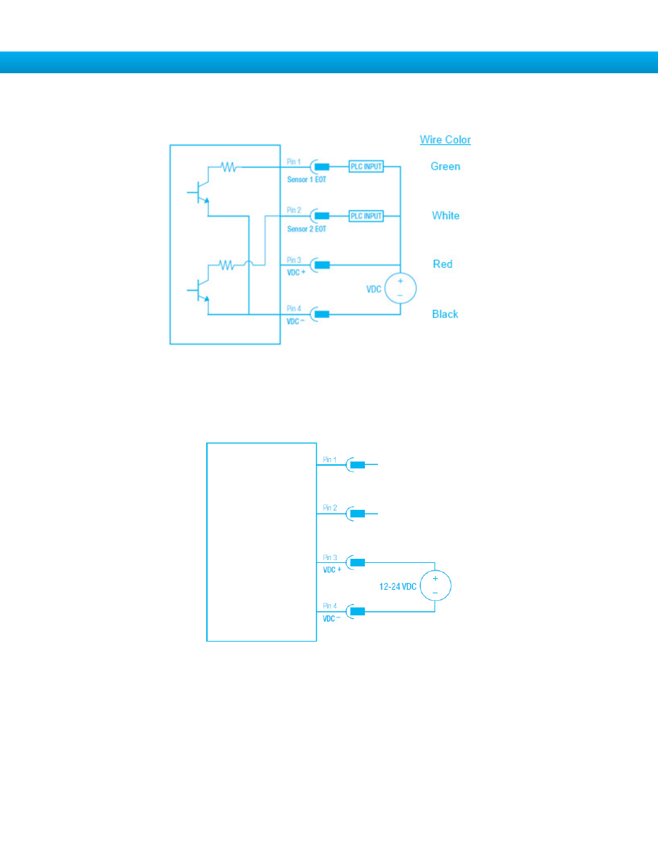
To use the 2 EOT outputs of the IntelliSense
®
SIM unit, confirm DIP switch 9 is OFF and use the following the dia-
gram:
Figure 57: I/O connector output wiring diagram with wire colors for cable CBL-IS-CF-0.5
Note: PLC input needs to accept sinking (NPN) sensors.
To use the I/O Connector to power SIM, confirm DIP switch 9 is ON and follow the diagram below.
Figure 58: I/O connector SIM power wiring diagram