Intellisense, Manual – Bimba IntelliSens User Manual
Page 46
IntelliSense
®
Manual
46
The IntelliSense
®
SIM also stores the Real Time Clock Data and Identification labels, configured by the user, as ASCII
data in the following registers:
Table 5: ASCII MODBUS Registries
Using IntelliSense
®
I/O Connector
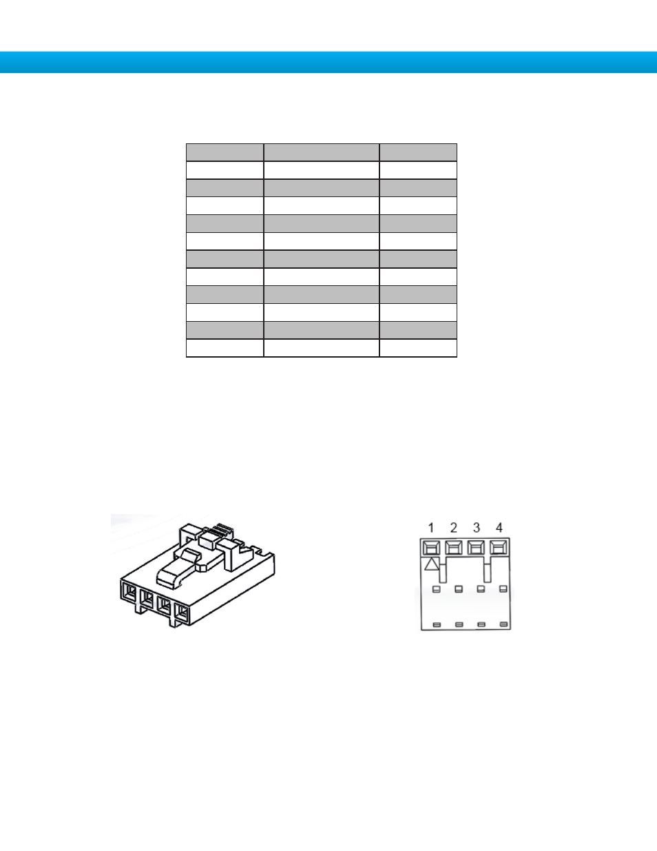
The IntelliSense
®
SIM unit’s I/O connector can be used to power the SIM or to utilize the two 3-wire NPN transis-
tor outputs. These outputs are configured to indicate the EOT (End Of Travel) sensed by the IntelliSense
®
system.
Cable part number CBL-IS-CF-0.5 is used to connect to the I/O connector. This cable is 0.5 meter in length, has
flying leads on one end, and a 4 pin connector on the other (Figure 55: Molex 50-57-9409 connector). The underside
of this connector has an arrow to indicate the location of pin 1 (Figure 56: Underside of Molex connector with Pin 1
Indicator).
User may also purchase the 4 pin connector through a 3
rd
party to wire for additional lengths as needed.
Figure 55: Molex 50-57-9409 connector
Figure 56: Underside of Molex connector with Pin 1 Indicator
Register
Description
Size
40501
RTC Seconds
2 bytes
40502
RTC minutes
2 bytes
40503
RTC hours (24hr)
2 bytes
40504
RTC hours (12hr)
2 bytes
40505
RTC AM/PM
2 bytes
40506
RTC day
2 bytes
40507
RTC month
2 bytes
40508
RTC year (last 2 digits)
2 bytes
40510
ID 1 string
60 bytes
40540
ID 2 string
40 bytes
40560
Part number
30 bytes