American Energy Systems O2 Catalytic User Manual
Page 39
39
BLOWER THEORY OF OPERATION
All Country Flame catalytic stoves come standard or have optional room air blower systems available. These room air
blower systems are designed to pull cool air from the living space into, through, and across the hot catalytic stove body
thereby returning the exchanged air to the home at an elevated temperature (heated). These blower systems add to the
overall heating efficiency by ensuring that a stove does not rely solely on heat convection to provide warmth to a home. It
is important to note that in the event of a power outage, all Country Flame catalytic stoves will continue to operate
properly and no damage should occur to the blower system from over heating.
All Country Flame blower systems are designed to turn on and off automatically as the temperatures rise and fall inside
the firebox. The blower systems are automated with a thermal 110° F snap disk installed in the blower’s electrical system.
This thermally activated switch automatically turns the blower on and off. The blower is turned on as the air surrounding
the snap disk reaches approximately 110° F. As the air temperature rises, the thermal snap disk closes, completing the
electrical circuit thus allowing the fan motor to be activated. Household air is pulled into the stove, heated, and then
returned back to the home. In the event the home air temperature drops below approximately 90° F, the switch
deactivates, turning off the stove blowers.
The following information and schematics are provided for informational purposes only. A qualified electrician should
perform all repairs or installation of the electrical power required for Country Flame stoves.
WARNING: Lethal electrical power is present in home electrical circuits. All Country Flame stoves require standard
household power at 120 volts, 60 Hz, and 15 amperes. This standard household power should be provided through a
National Electric Code approved 3-wire power outlet that is properly grounded. Installing house wiring incorrectly,
failing to maintain proper polarity in either the plug or receptacle, or removing the grounding pin can lead to potentially
fatal shock hazards. Country Flame strongly recommends the use of a qualified electrician to install, maintain, or service
any part of a stove’s electrical system.
The schematics provided on the next several pages are for informational purposes. Changes do occur from time to time
on stove wiring systems and Country Flame reserves the right to update and change the schematic at its discretion. In the
event of any discrepancy between the information provided and the actual wiring of a stove, please contact Country Flame
or one of its local dealers.
MODEL O2
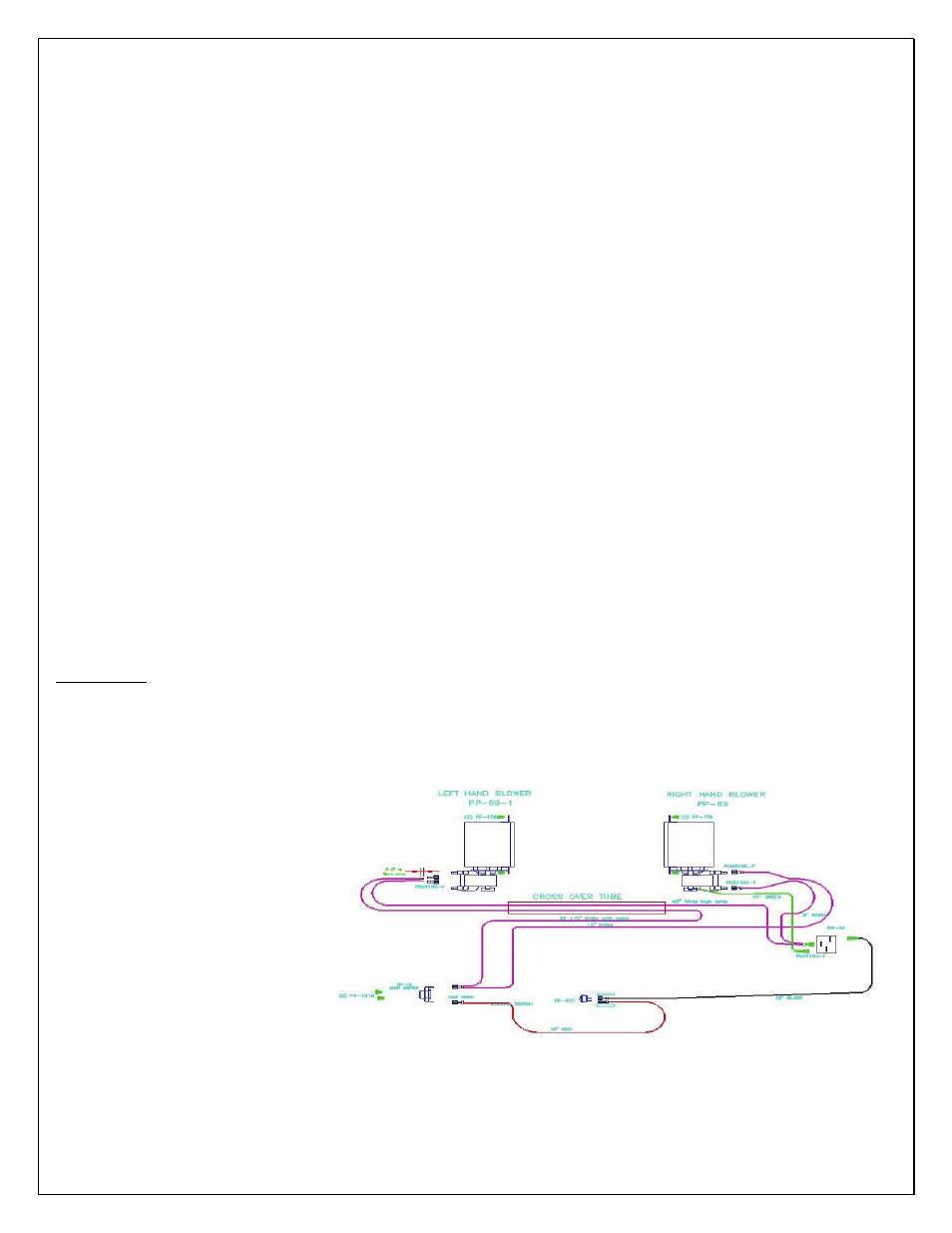
The Model O2 catalytic stove comes standard with a two-blower system. FIGURE 22 shows the electrical schematic of
the Model O2 blower system. One blower is mounted on the left side and one blower is mounted on the right side of the
stove. Each of these blowers pull room air into a cavity and push it to the back and then into the top cavity of the Model
O2 stove. As the air passes around this cavity and comes out the top of the stove, it picks up heat to warm the home. The
fans are designed to run continuously once the thermal snap disk closes and completes the electrical circuit.
BLOWER CARE: At least once a
season (light use) and every six
months (heavy use), the fan blades
should be removed and cleaned. The
motors should receive proper oiling at
this time. Cleaning the squirrel cages
can be done by brushing or blowing
them off. The motors should be
lubricated annually with an approved
electric motor lubricant. Lubricate
with 10 to 20 drops of Anderol
Number 465 high temperature
synthetic lubricant. DO NOT USE
petroleum-based oil, as premature bearing failure will result.
FIGURE 22: MODEL O2 BLOWER SYSTEM ELECTRICAL DIAGRAM