9 i2s1, 10 i2s2, 11 i2s3 – ADLINK LEC-BASE R1 User Manual
Page 20: I2s1
14
Interface Signals
2.1.9
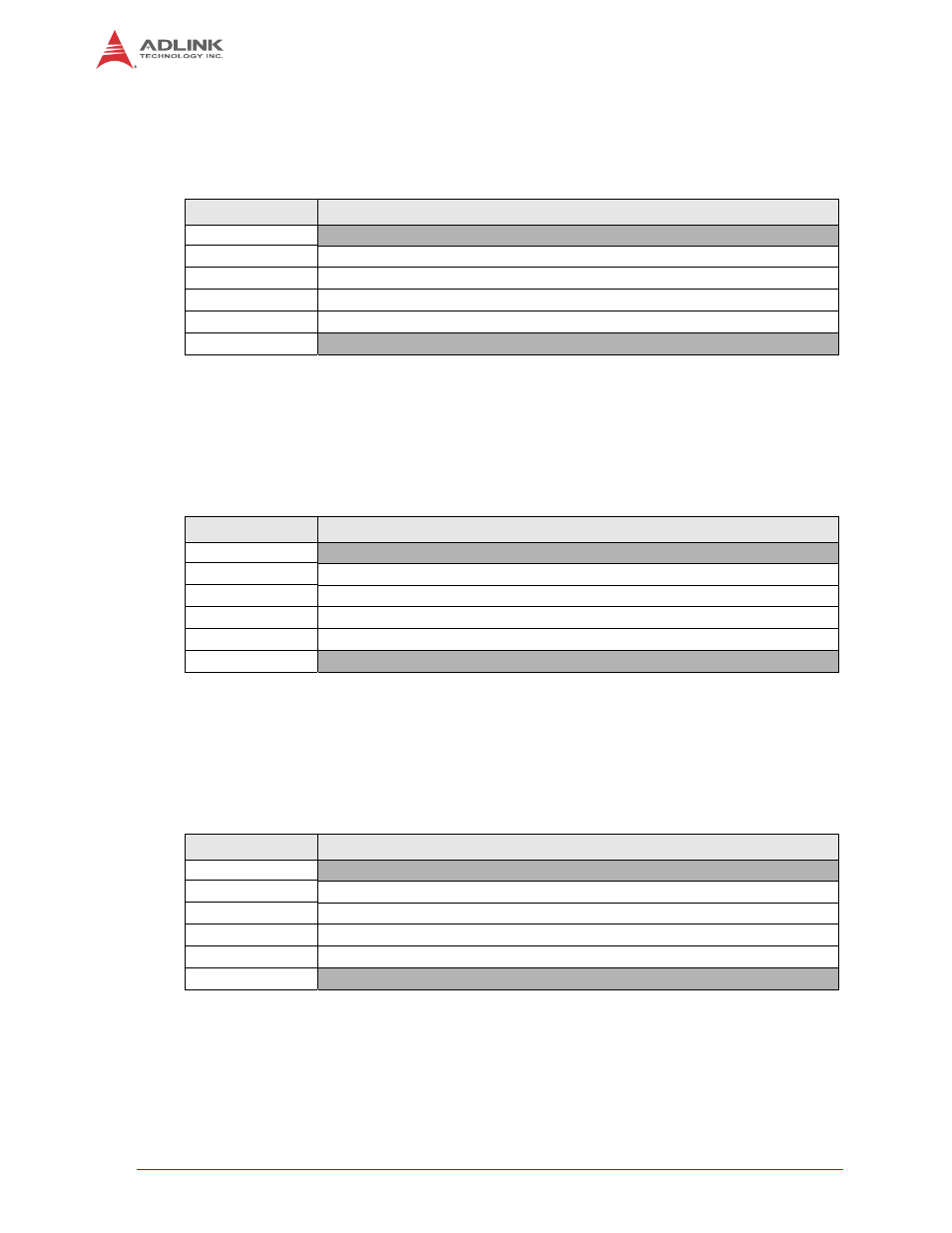
I2S1
Table 2-13 lists the pin signals of the I2S1 header, which provides 6 pins in a single row with
0.098" (2.50mm) pitch. These pins are connected to the SMARC connector over the 3.3 volt
level shifter.
NOTE: Shaded table cells denote power or ground.
2.1.10
I2S2
Table 2-14 lists the pin signals of the I2S2 header, which provides 6 pins in a single row with
0.098" (2.50mm) pitch. These pins are connected to the SMARC connector over the 3.3 volt
level shifter.
NOTE: Shaded table cells denote power or ground.
2.1.11
I2S3
Table 2-15 lists the pin signals of the I2S3 header, which provides 6 pins in a single row with
0.098" (2.50mm) pitch. These pins are connected to the SMARC connector over the 3.3 volt
level shifter.
NOTE: Shaded table cells denote power or ground.
Table 2-13: I2S1 Signals (I2S1)
Pin #
Signal
1
VDD_3V3
2
MCBSP1_FSX_3V (connected to SMARC pin S39)
3
MCBSP1_DX_3V (connected to SMARC pin S40)
4
MCBSP1_DR_3V (connected to SMARC pin S41)
5
MCBSP1_CLKX_3V (connected to SMARC pin S42)
6
GND
Table 2-14: I2S2 Signals (I2S2)
Pin #
Signal
1
VDD_3V3
2
MCBSP2_FSX_3V (connected to SMARC pin S43)
3
MCBSP2_DX_3V (connected to SMARC pin S44)
4
MCBSP2_DR_3V (connected to SMARC pin S45)
5
MCBSP2_CLKX_3V (connected to SMARC pin S46)
6
GND
Table 2-15: I2S3 Signals (I2S3)
Pin #
Signal
1
VDD_3V3
2
MCBSP3_FSX_3V (connected to SMARC pin S50)
3
MCBSP3_DX_3V (connected to SMARC pin S51)
4
MCBSP3_DR_3V (connected to SMARC pin S52)
5
MCBSP3_CLKX_3V (connected to SMARC pin S53)
6
GND