5 controller area network (can1), 6 cell charger/battery supply (cn4), Controller area network (can1) – ADLINK LEC-BASE R1 User Manual
Page 18: Cell charger/battery supply (cn4)
12
Interface Signals
2.1.5
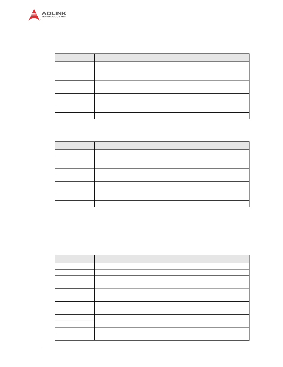
Controller Area Network (CAN1)
Table 2-8 and Table 2-9 list the pin signals of the Controller Area Network interface (CAN1A and
CAN1B), which provides standard dual DB9 connectors.
NOTE: These pins are connected over the CAN transceiver to the CAN0 SMARC connector
interface (pins P143 and P144.)
NOTE: These pins are connected over the CAN transceiver to the CAN1 SMARC connector
interface (pins P145 and P146.)
2.1.6
Cell Charger/Battery Supply (CN4)
Table 2-10 lists the pin signals of the Cell Charger/Battery Supply header, which provides 12
pins in 2 rows, odd/even pin sequence (1, 2), and 0.079" (2.00mm) pitch.
Table 2-8: Controller Area Network Signals (CAN1A)
Pin #
Signal
1
Not Connected
2
CAN1_H
3
Not Connected
4
Not Connected
5
GND
6
Not Connected
7
CAN1_L
8
Not Connected
9
5 Volt
Table 2-9: Controller Area Network Signals (CAN1B)
Pin #
Signal
1
Not Connected
2
CAN2_H
3
Not Connected
4
Not Connected
5
GND
6
Not Connected
7
CAN2_L
8
Not Connected
9
5 Volt
Table 2-10: Cell Charger/Battery Supply (CN4)
Pin #
Signal
1
Therm1
2
+VE
3
Cell_4 (positive terminal of); connected to pins 2, 4, 6
4
+VE
5
Cell_3 (positive terminal of)
6
+VE
7
Cell_2
(positive terminal of)
8
-VE
9
Cell_1 (positive terminal of)
10
-VE
11
-VE (negative terminal of); connected to pins 8, 10, 12
12
-VE