ADLINK LEC-BASE R1 User Manual
Page 12
6
Overview
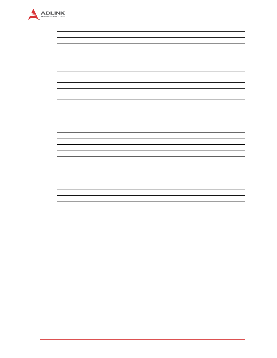
LED12
Cell Protection IC
Green LED indicating battery pack conditions
LED13
Cell Protection IC
Green LED indicating battery pack conditions
LED14
Cell Protection IC
Green LED indicating battery pack conditions
LED15
Cell Protection IC
Green LED indicating battery pack conditions
LED16
Power
Green LED indicating power asserted to baseboard
MINIPCIE1
PCIE Mini Card
52-pin, standard, right-angle socket for PCI Express Mini
Card
MINIPCIE2
PCIE Mini Card
52-pin, standard, right-angle socket for PCI Express Mini
Card
PC1
TTL Panel Control
6-pin header for control signals to flat panel display
PCIE1
PCI Express
36-pin, standard edge connector for x1 PCI Express
interface
PWM1
Power Management
14-pin header for Power Management signals
PWRON1
Power On
4-pin, push-button switch to turn on 12V to baseboard
PWRON2
Power On
4-pin, push-button switch to assert POWER_nBTN signal
for SMARC connector
SATA1
SATA
7-pin, standard Serial ATA connector with attached 15-pin
power connection
SD2
SD Card Slot
Standard slot connector for Secure Digital memory card
SIM1
SIM Slot
Standard slot connector for Subscriber Identity Module
SIM2
SIM Slot
Standard slot connector for Subscriber Identity Module
SPDIF1
SPDIF-OUT Audio
Standard connector for SPDIF digital audio interface
SPI0
System Packet
Interface
5-pin header for SPI interface
SPI1
System Packet
Interface
4-pin header for SPI interface
SW15
Reset Switch
Push-button switch to warm reset the module
USBC1
USB
4-stack, standard USB 2.0 connector
USB1
Micro-USB
Standard connector for micro-USB interface, OTG
USB2
USB
Standard connector for single USB 2.0 interface
Table 1-2: Header, Switch, LED, and Connector Descriptions (Continued)