ADLINK LEC-BASE R1 User Manual
Page 10
4
Overview
1.3
Interface Headers, Jumper Headers, Switches, LEDs, and Connectors
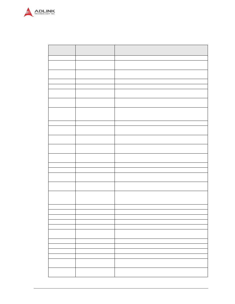
Table 1-2 describes the headers, switches, LEDs, and connectors for the LEC-BASE baseboard
shown in Figure 1-3.
Table 1-2: Header, Switch, LED, and Connector Descriptions
Header /
Connector#
Signal / Device
Description
AFB2 SD/eMMC
Card
60-pin
terminal for eMMC card
AJ1
Audio Jack
32-pin standard audio jack for three audio interfaces: Line
In (Blue), Line Out (Green), and MIC In (Pink)
ANT1
GPS Antenna
3-pin, radio frequency, 50 ohm antenna for receiving GPS
signals
CAM0
Camera
10-pin header for MIPI CSI1 camera
CAM1
Camera
10-pin header for MIPI CSI0 camera
CAM3
Camera Control
10-pin header for I2C clock/data signals on MIPI CSI
camera
CAN1 (two
ports)
CAN Bus
Dual, 9-pin standard DB9 connectors for transmitting and
receiving Controller Area Network signals
CN1
Touch Screen
4-pin, standard connector for 4-wire resistive touch
controller (not for TTL USB-based touch screen controller
in Starter Kit)
CN2
microSD
12-pin, standard socket for microSD memory cards
CN4
Cell Charger/Battery
Supply
12-pin header for 2-cell, raw lithium ion battery interface to
power the baseboard
CN5
MiniDin DC Jack
4-pin, female connector for additional power input for
auxiliary circuitry
COM1 (two
ports)
UART
Dual, 9-pin standard DB9 connectors for RS232 serial
ports
COM2 (two
ports)
UART
Dual, 9-pin standard DB9 connectors for RS232 serial
ports
GPIO1
GPIO
12-pin header for General Purpose IO
H25
Battery2
9-pin header for smart battery connection
I2S1
I2S Devices
6-pin header for I2S devices such as audio CODECs,
baseband modems, and touch controllers
I2S2
I2S Devices
6-pin header for I2S devices such as audio CODECs,
baseband modems, and touch controllers
I2S3
I2S Devices
6-pin header for I2S devices such as audio CODECs,
baseband modems, and touch controllers (designated also
for HD Audio CODECs)
J1
SMARC Interface
314-pin, MXM socket for Memory, Video, and I/O functions
J3
TTL
34-pin header for VGA LCD flat panel output
J6
HDMI1
19-pin, standard HDMI micro connector
J8
LVDS
34-pin header for LVDS output
J9 (AFB1)
Auxiliary Devices
34-pin header for differential pair and data bit signals
J10
I2C
2-pin header for general purpose, level-shifted 3.3V, I2C
clock and data signals for the module
J11
HDMI2
19-pin, standard HDMI micro connector
J12
Battery
2-pin header for RTC external battery
J14
LVDS Control
8-pin header for LVDS panel and backlight control
JACK1
DC Power
6-pin, standard, right-angle 19V center-pin, DC power jack
JP2
LCD Power Select
3-pin, jumper header for LCD 3.3V (1-2) or 5V (2-3) power
selection
JP3
I2C Select
3-pin, jumper header to select I2C_LCD (clock/data pair)
for HDMI controller (1-2 default)