Jp3/jp7, Jp1/jp2 jp5/jp9 – ADLINK ACL-6128A User Manual
Page 21
Installation
• 13
2.6.3 Summary
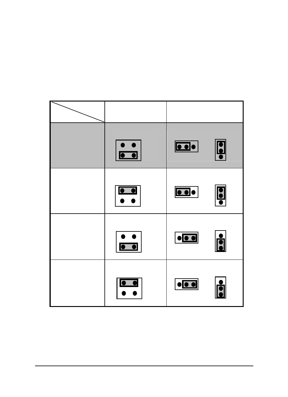
Users can configure the output voltage of CH1 and CH2 for application specific
needs according to the reference source and output range settings. can follow
the below table to. Settings are listed in two separate tables for the ACL-6128A
and ACL-6128, respectively.
(JP1, JP3, and JP5 are for CH1. JP2, JP7, and JP9 are for CH2)
ACL-6128A settings (Note: this table is for the ACL-6128A ONLY.)
Jumper
Output Range
JP3 for CH1
JP7 for CH2
JP1 & JP5 for CH1
JP2 & JP9 for CH2
0 to +5V
Unipolar
(Default)
JP3/JP7
-10
-5
JP1/JP2 JP5/JP9
UP
BP
UP
BP
0V to +10V
Unipolar
JP3/JP7
-10
-5
JP1/JP2 JP5/JP9
UP
BP
UP
BP
-5V to +5V
Bipolar
JP3/JP7
-10
-5
JP1/JP2 JP5/JP9
UP
BP
UP
BP
-10V to +10V
Bipolar
JP3/JP7
-10
-5
JP1/JP2 JP5/JP9
UP
BP
UP
BP
- USB-1901 (84 pages)
- USB-1210 (54 pages)
- USB-2401 (60 pages)
- USB-7230 (50 pages)
- USB-2405 (56 pages)
- DAQe-2010 (92 pages)
- DAQe-2204 (100 pages)
- DAQe-2213 (94 pages)
- DAQe-2501 (74 pages)
- PXI-2010 (84 pages)
- PXI-2020 (60 pages)
- PXI-2501 (62 pages)
- cPCI-9116 (98 pages)
- ACL-8112 Series (93 pages)
- ACL-8112 Series (94 pages)
- ACL-8112 Series (92 pages)
- ACL-8216 (75 pages)
- ACL-8111 (61 pages)
- PCM-9112+ (10 pages)
- PCM-9112+ (94 pages)
- cPCI-6216V (47 pages)
- ACL-6126 (28 pages)
- PCM-6308V+ (52 pages)
- PCM-6308V+ (4 pages)
- PCI-7444 (82 pages)
- PCI-7434 (48 pages)
- PCI-7234 (56 pages)
- PCI-7260 (66 pages)
- PCI-7258 (38 pages)
- PCI-7256 (48 pages)
- PCI-7250 (48 pages)
- LPCI-7250 (48 pages)
- PCI-7396 (65 pages)
- PCI-7296 (59 pages)
- PCI-8554 (67 pages)
- PCIe-7360 (94 pages)
- PCIe-7350 (86 pages)
- PCIe-7300A (114 pages)
- PCIe-7200 (51 pages)
- PCI-7300A (112 pages)
- PCI-7300A (83 pages)
- PCI-7200 (96 pages)
- cPCI-7300 (83 pages)
- cPCI-7300 (82 pages)