4 jumper and dip switch description – ADLINK ACL-6128A User Manual
Page 15
Installation
• 7
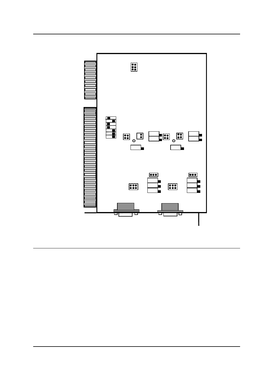
2.3 ACL-6128A's
Layout
CN1
CN2
SW
1
JP
1
JP
2
VR
4
V
R5
V
R6
JP
5
JP
6
VR
3
VR
1
VR
2
JP
3
JP
4
TB
1
6128A
I
s
o
lat
ed
2CH D/
A
A
CRD
VR
9
VR
7
VR
8
JP
7
JP
8
TB
2
VR
1
0
VR
1
1
VR
1
2
JP
9
JP
10
Figure 2.1 ACL-6128A‘s Layout
2.4 Jumper and DIP Switch Description
You can change the ACL-6128A's channels and base address by setting
jumpers and DIP switches on the card. The card's jumpers and switches are
preset at the factory. Under normal circumstances, these settings should not
need to be changed.
A jumper switch is closed or "shorted" with the plastic cap inserted over two
pins of the jumper. A jumper is open when the plastic cap inserted over one or
no pin(s) of the jumper.
See also other documents in the category ADLINK Hardware:
- USB-1901 (84 pages)
- USB-1210 (54 pages)
- USB-2401 (60 pages)
- USB-7230 (50 pages)
- USB-2405 (56 pages)
- DAQe-2010 (92 pages)
- DAQe-2204 (100 pages)
- DAQe-2213 (94 pages)
- DAQe-2501 (74 pages)
- PXI-2010 (84 pages)
- PXI-2020 (60 pages)
- PXI-2501 (62 pages)
- cPCI-9116 (98 pages)
- ACL-8112 Series (93 pages)
- ACL-8112 Series (94 pages)
- ACL-8112 Series (92 pages)
- ACL-8216 (75 pages)
- ACL-8111 (61 pages)
- PCM-9112+ (10 pages)
- PCM-9112+ (94 pages)
- cPCI-6216V (47 pages)
- ACL-6126 (28 pages)
- PCM-6308V+ (52 pages)
- PCM-6308V+ (4 pages)
- PCI-7444 (82 pages)
- PCI-7434 (48 pages)
- PCI-7234 (56 pages)
- PCI-7260 (66 pages)
- PCI-7258 (38 pages)
- PCI-7256 (48 pages)
- PCI-7250 (48 pages)
- LPCI-7250 (48 pages)
- PCI-7396 (65 pages)
- PCI-7296 (59 pages)
- PCI-8554 (67 pages)
- PCIe-7360 (94 pages)
- PCIe-7350 (86 pages)
- PCIe-7300A (114 pages)
- PCIe-7200 (51 pages)
- PCI-7300A (112 pages)
- PCI-7300A (83 pages)
- PCI-7200 (96 pages)
- cPCI-7300 (82 pages)
- cPCI-7300 (83 pages)