Jp1 jp5, Jp2 jp9 – ADLINK ACL-6128A User Manual
Page 20
12
• Installation
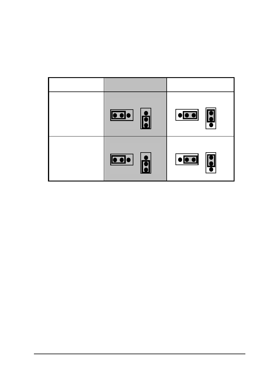
ACL-6128 settings (Note: These settings are for the older ACL-6128 only.
Jumper settings for the newer ACL-6128 are slightly different—see above. Also,
JP9 on the PCB of the older ACL-6128 ONLY is mislabeled. “BP” is the top pin
and “UP” is the bottom pin.)
Channel No.
Unipolar
( Default )
Bipolar
CH1
JP1
JP5
UP
BP
BP
UP
JP1
JP5
UP
BP
UP
BP
CH2
JP2
JP9
UP
BP
UP
BP
JP2
JP9
UP
BP
BP
UP
Figure 2.5 Output Range Setting
See also other documents in the category ADLINK Hardware:
- USB-1901 (84 pages)
- USB-1210 (54 pages)
- USB-2401 (60 pages)
- USB-7230 (50 pages)
- USB-2405 (56 pages)
- DAQe-2010 (92 pages)
- DAQe-2204 (100 pages)
- DAQe-2213 (94 pages)
- DAQe-2501 (74 pages)
- PXI-2010 (84 pages)
- PXI-2020 (60 pages)
- PXI-2501 (62 pages)
- cPCI-9116 (98 pages)
- ACL-8112 Series (93 pages)
- ACL-8112 Series (94 pages)
- ACL-8112 Series (92 pages)
- ACL-8216 (75 pages)
- ACL-8111 (61 pages)
- PCM-9112+ (94 pages)
- PCM-9112+ (10 pages)
- cPCI-6216V (47 pages)
- ACL-6126 (28 pages)
- PCM-6308V+ (52 pages)
- PCM-6308V+ (4 pages)
- PCI-7444 (82 pages)
- PCI-7434 (48 pages)
- PCI-7234 (56 pages)
- PCI-7260 (66 pages)
- PCI-7258 (38 pages)
- PCI-7256 (48 pages)
- PCI-7250 (48 pages)
- LPCI-7250 (48 pages)
- PCI-7396 (65 pages)
- PCI-7296 (59 pages)
- PCI-8554 (67 pages)
- PCIe-7360 (94 pages)
- PCIe-7350 (86 pages)
- PCIe-7300A (114 pages)
- PCIe-7200 (51 pages)
- PCI-7300A (112 pages)
- PCI-7300A (83 pages)
- PCI-7200 (96 pages)
- cPCI-7300 (83 pages)
- cPCI-7300 (82 pages)