6 selecting d/a range and functions – ADLINK ACL-6128A User Manual
Page 18
10
• Installation
2.6 Selecting D/A Range and Functions
There are two factors will effect the output voltage of ACL-6128A: reference
source and output range.
2.6.1
Reference Source Setting
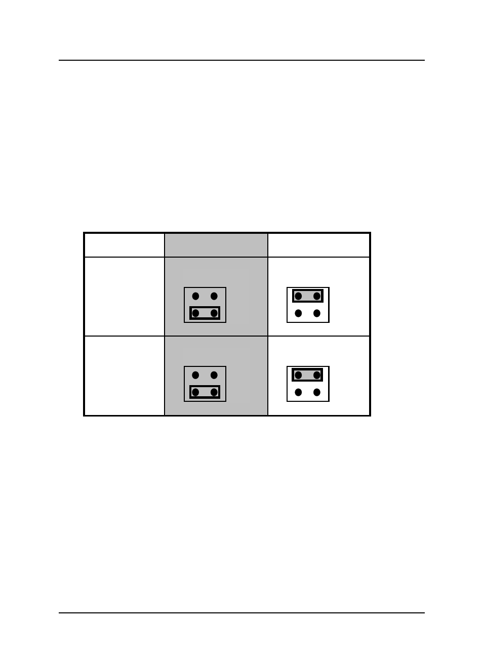
The ACL-6128A D/A converter reference voltage source can be internally
generated or an external reference voltage from the Reference Voltage Input
(REF.IN) of connectors CN1 and CN2. The settings of the reference sources
for CH1 and CH2 are controlled by jumpers JP4 and JP8, respectively. The
default setting is Internal Reference for both CH1 and CH2, and is illustrated
below.
Internal Reference
( Default )
External Reference
Voltage
CH1
JP4
EXT
INT
JP4
EXT
INT
CH2
JP8
EXT
INT
JP8
EXT
INT
Figure 2.3 Reference Source Setting
After setting as internal reference source, two fixed precision internal -5V and -
10V reference sources are provided by ACL-6128A. The source selection is set
by JP3 (CH1) and JP7 (CH2), and the default setting of internal reference
voltage is -5V, which is illustrated as Figure 2.4 below: