Jp1 jp5, Jp2 jp9 – ADLINK ACL-6128A User Manual
Page 19
Installation
• 11
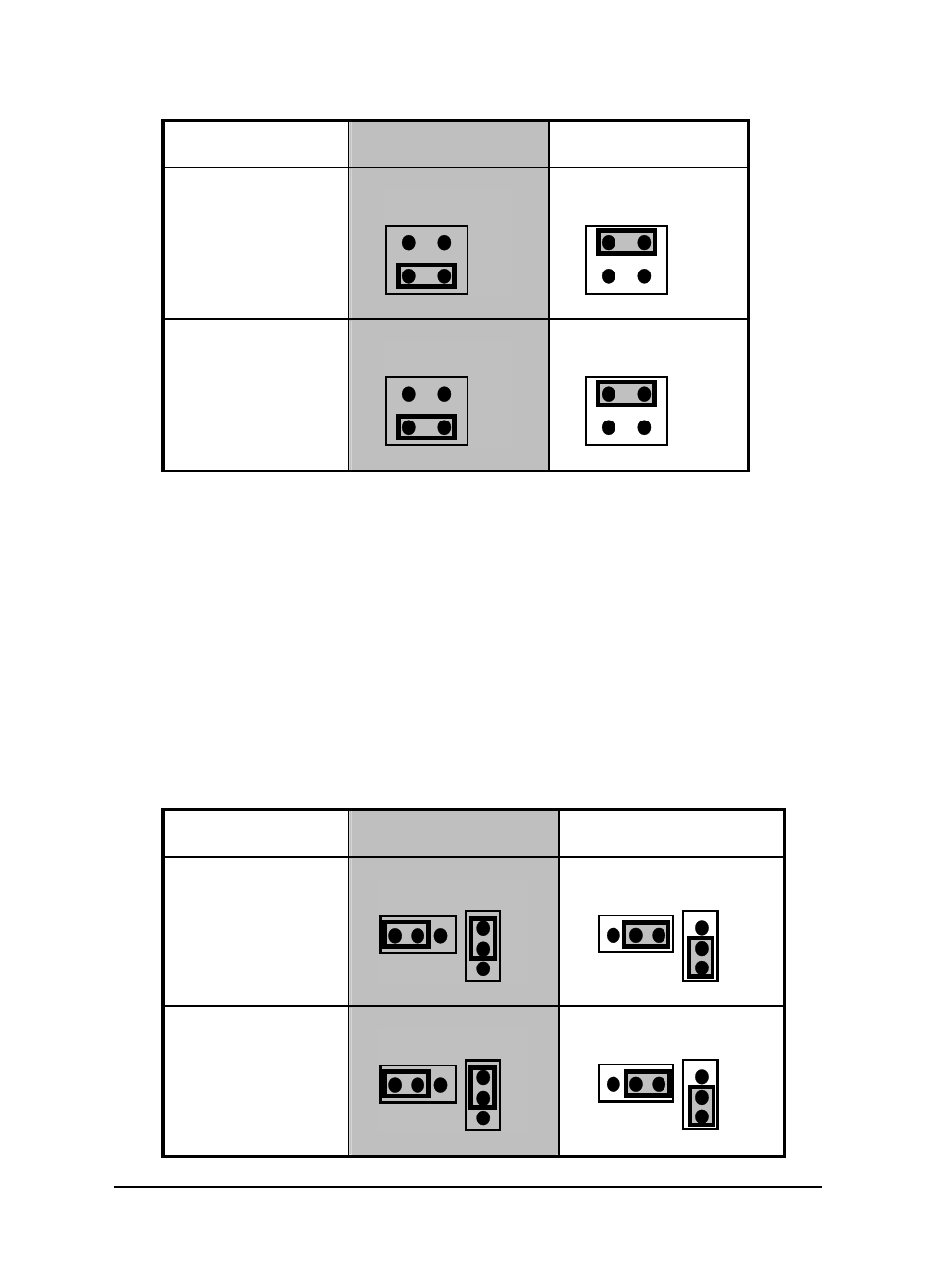
Channel No.
Internal -5V
( Default)
Internal -10V
CH1
JP3
-10
-5
JP3
-10
-5
CH2
JP7
-10
-5
JP7
-10
-5
Figure 2.4 Internal Reference Voltage Setting
If users choose the external reference, both AC and DC voltage sources can
be used by the external reference. The maximum input voltage is +/- 10V. The
voltage sources can be input through Pin 3 of the CN1 and CN2 connectors.
2.6.2
Output Range Setting
The output voltage range of ACL-6128A can be set either Bipolar or Unipolar.
The jumpers, JP1 and JP5 (for CH1), and JP2 and JP9 (for CH2) are used for
the settings as illustrated in Figure 2.5 below (ACL-6128A and ACL-6128
respectively):
ACL-6128A settings (Note: These settings are for the ACL-6128A only.
Jumper settings for the older ACL-6128 are slightly different—see below.)
Channel No.
Unipolar
( Default )
Bipolar
CH1
JP1 JP5
UP
BP
UP
BP
JP1 JP5
UP
BP
UP
BP
CH2
JP2 JP9
UP
BP
UP
BP
JP2 JP9
UP
BP
UP
BP