10 mode 10: pwm output, Mode 10: pwm output, Figure 4-26 – ADLINK USB-1903 User Manual
Page 77: Mode 9-edge separation measurement, Figure 4-27, Mode 10-pwm output
Operation
63
USB-1900 Series
clock frequency. The maximum counting width is 32-bit. Decrease
of the counter value in Edge Separation Measurement mode is
shown.
Figure 4-26: Mode 9-Edge Separation Measurement
4.8.10
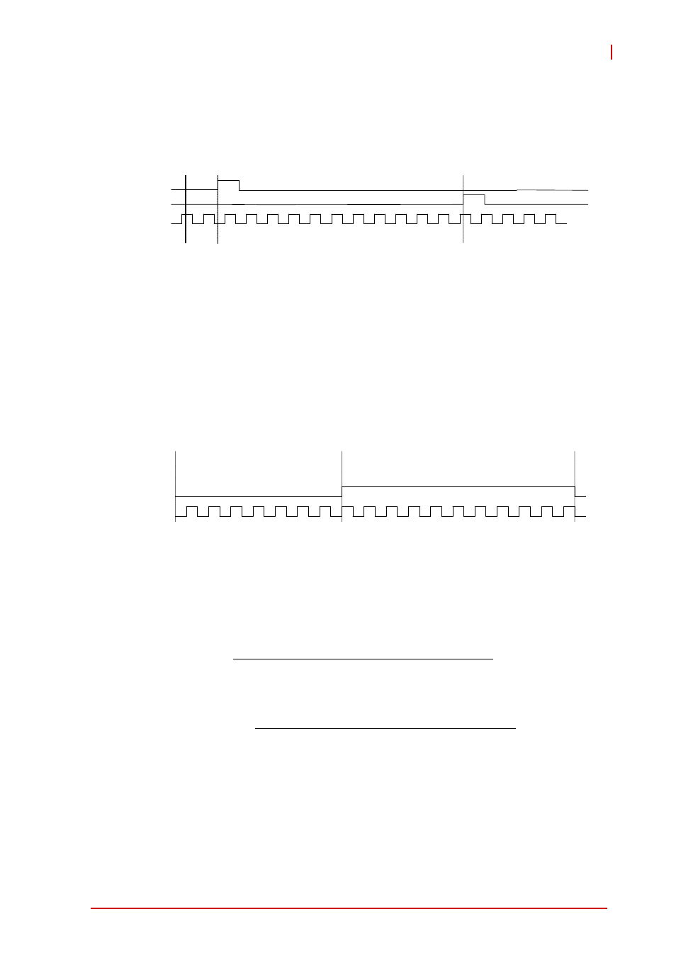
Mode 10: PWM Output
The USB-1900 Series timer/counter can also simulate a PWM
(Pulse Width Modulation) output. By setting a varying amount of
Pulse_initial_cnt and Pulse_length_cnt, varying pulse frequencies
(Fpwm) and duty cycles (Dutypwm) can be obtained. PWM output
is shown.
Figure 4-27: Mode 10-PWM Output
Calculation of the PWM frequency and duty cycle is as follows.
1 3
1 3
1 2
1 1
9
8
7
6
S o f t w a r e s t a r t
5
4
3
2
1
1
1
1
1
1
G a t e
C L K
A U X
C o u n t v a l u e
1 0
T I M E B A S E
P W M O U T
P u l s e _ I n i t i a l _ c n t
= 0 x 7
P u l s e _ I e n g t h _ c n t = 0 x B
cnt
length
Pulse
cnt
initial
Pulse
cnt
length
Pulse
Duty
cnt
length
Pulse
cnt
initial
Pulse
F
F
PWM
Tim ebase
PWM
_
_
_
_
_
_
_
_
_
_
+
=
+
=