1 bipolar output modes, 2 software update, 3 waveform generation – ADLINK USB-1903 User Manual
Page 62: Bipolar output modes, Software update, Waveform generation, Table 4-2: bipolar output code
48
Operation
4.5.1
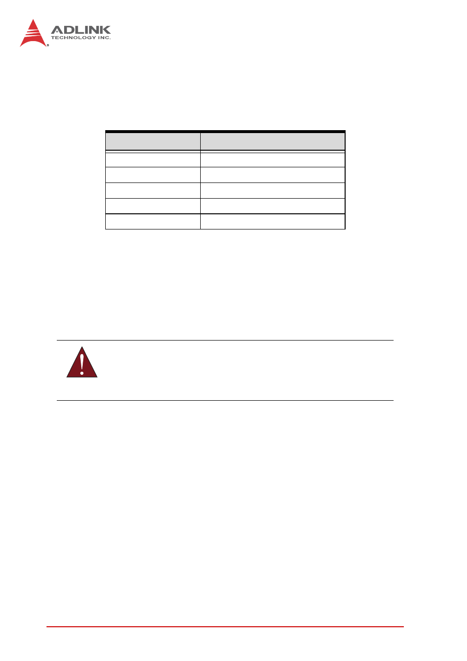
Bipolar Output Modes
The USB-1900 Series supports a maximum ±10 V voltage output.
The relationship of straight binary coding between the digital
codes and output voltages is as shown.
Table 4-2: Bipolar Output Code
4.5.2
Software Update
This method is indicated when there is a need to generate D/A
output controlled by user programs. In this mode, the D/A con-
verter generates one output once the software command is
issued.
4.5.3
Waveform Generation
Waveform Generation Data Structure
FIFO is a hardware first-in first-out data queue that holds tem-
porary digital codes for D/A conversion. When the USB-1900
Series operates in waveform generation mode, the waveform
patterns are stored in FIFO with 10k samples. Continuous
mode transfers data according to channel order. DA channel 0
to channel 1 data is shown.
Digital Code
Analog Output
0x7FFF
+9.999695 V (+10 V - 1 LSB)
0x0001
+0.000305 V (1 LSB)
0x0000
0 V
0xFFFF
-0.000305 V (0 V – 1 LSB)
0x8000
-10 V
WARNING:
Difficulty in determining the software update rate may occur
within a multitasking environment such as Windows.