5 waveform generation trigger modes, Waveform generation trigger modes, Figure 4-14 – ADLINK USB-1903 User Manual
Page 66: Post-trigger waveform generation
52
Operation
External Digital Triggering
An external digital trigger occurs when a rising edge or falling
edge is detected on the digital signal connected to the AOTG
(Analog output trigger) pin, as shown. Users can program the
trigger polarity through ADLINK software. The signal level of
the external digital trigger signals should be TTL-compatible,
and the minimum pulse 20 ns.
4.5.5
Waveform Generation Trigger Modes
The analog output supports post, delay, post trigger with retrigger,
and delay trigger with retrigger modes.
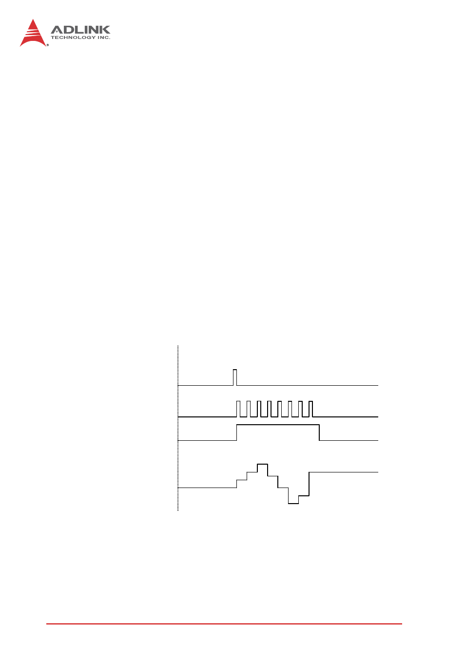
Post-Trigger Waveform Generation
Post-trigger generation is indicated to generate a waveform
immediately following a trigger signal. The number of patterns
to be updated after the trigger signal is specified by
UC_counter * IC_counter, as shown.
Figure 4-14: Post-Trigger Waveform Generation
(UC _Counter=8, IC_Counter=1)
8 update counts, 1 iteration
DAWR
WFG_in_progress
Operation start
Trigger
Output Waveform
0
2
4
6
3
- 4
- 2
4