6 mode 6: re-triggered single pulse generation, Mode 6: re-triggered single pulse generation, Figure 4-22 – ADLINK USB-1903 User Manual
Page 75: Mode 5-single-triggered pulse, Figure 4-23, Mode 6-re-triggered single pulse, Gate clk count value out software start, Figure 4-22: mode 5-single-triggered pulse, Figure 4-23: mode 6-re-triggered single pulse
Operation
61
USB-1900 Series
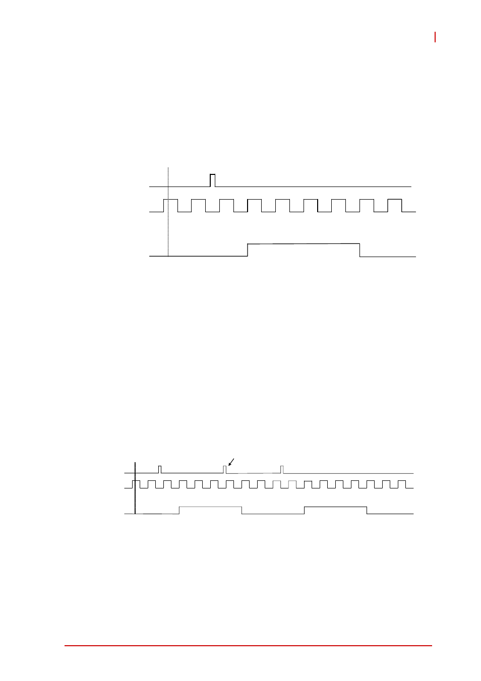
periods of the GPTC_CLK input. When the first GPTC_GATE
edge triggers the single pulse, GPTC_GATE has no effect until
software start is executed again. Generation of a single pulse with
a pulse delay of two and a pulse-width of four is shown.
Figure 4-22: Mode 5-Single-Triggered Pulse
4.8.6
Mode 6: Re-Triggered Single Pulse Generation
This mode is similar to Mode 5 except that the counter generates
a pulse following every active edge of GPTC_GATE. After soft-
ware start, every active GPTC_GATE edge triggers a single pulse
with programmable delay and pulse width. Any GPTC_GATE trig-
gers that occur when the prior pulse is not completed are ignored.
Generation of two pulses with a pulse delay of two and a pulse
width of four is shown.
Figure 4-23: Mode 6-Re-Triggered Single Pulse
2
2
1
0
3
2
1
0
Gate
CLK
Count value
OUT
Software start
2
2
1
0
3
2
1
0
2
2
1
0
3
2
1
0
2
2
G a t e
C L K
C o u n t v a l u e
O U T
S o f t w a r e s t a r t
I g n o r e d