Figure 4-15, Delayed-trigger waveform generation – ADLINK USB-1903 User Manual
Page 67
Operation
53
USB-1900 Series
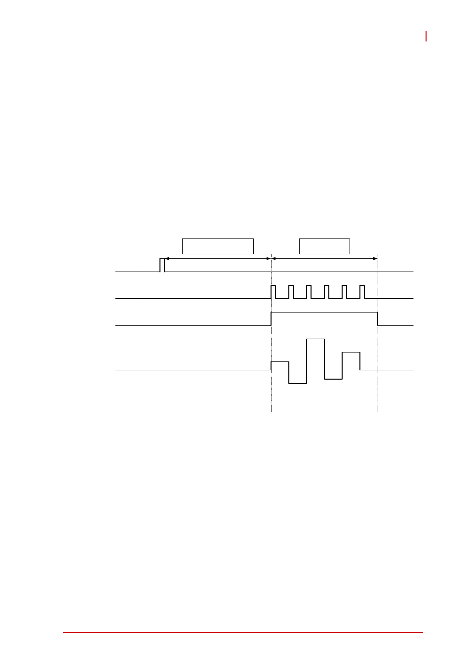
Delayed-Trigger Waveform Generation
Delayed-Triggering is indicated when waveform generation is
to be delayed after the trigger signal. The delay time is deter-
mined by DLY1_counter, as shown. The counter calculates
down on the rising edges of DLY1_counter clock source after
the start trigger signal. When the count reaches zero, the
waveform is generated. The DLY1_counter clock source can
be selected via software application using the internal 80 MHz
timebase.
Figure 4-15: Delayed-Trigger Waveform Generation
Post-Trigger or Delayed-Trigger with Retriggering
Post-trigger or delayed-trigger with retrigger modes are indi-
cated when multiple waveforms are to be generated with
respect to multiple incoming trigger signals. You can set
Trig_counter to specify the number of acceptable trigger sig-
nals, as shown.
In this example, two waveforms are generated after the first
trigger signal. The USB-1902/1903 then waits for another trig-
ger signal. When the next trigger signal is asserted, the
USB-1902/1903 generates two more waveforms.
UC_Counter = 6
6 update count and 1 iteration count
Trigger
DAWR
WF_in_Prog
Wave
Delay until DLY1_Counter
reaches 0