8 mode 8: continuous gated pulse generation, 9 mode 9: edge separation measurement, Mode 8: continuous gated pulse generation – ADLINK USB-1903 User Manual
Page 76: Mode 9: edge separation measurement, Figure 4-24, Mode 7-single-triggered continuous pulse, Figure 4-25, Mode 8-continuous gated pulse, 62 operation, Figure 4-25: mode 8-continuous gated pulse
62
Operation
4.8.7
Mode 7: Single-Triggered Continuous Pulse Generation
This mode is similar to Mode 5 except that the counter generates contin-
uous periodic pulses with programmable pulse interval and pulse-width
following the first active edge of GPTC_GATE. When the first
GPTC_GATE edge triggers the counter, GPTC_GATE has no effect until
software start is executed again. Generation of two pulses with a pulse
delay of four and a pulse-width of three is shown.
Figure 4-24: Mode 7-Single-Triggered Continuous Pulse
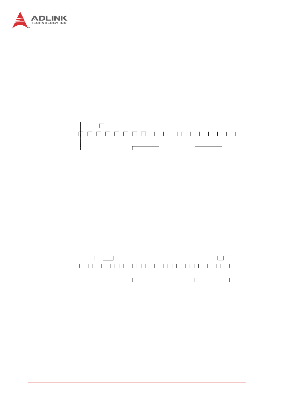
4.8.8
Mode 8: Continuous Gated Pulse Generation
This mode generates periodic pulses with programmable pulse interval
and pulse-width following software start. GPTC_GATE enables/disables
calculation. When GPTC_GATE is inactive, the counter halts the current
count value. Generation of two pulses with a pulse delay of four and a
pulse-width of three is shown.
Figure 4-25: Mode 8-Continuous Gated Pulse
4.8.9
Mode 9: Edge Separation Measurement
Measures the time differentiation between two different pulse signals.
The first pulse signal is connected to GPTC_GATE and the second signal
is connected to GPTC_AUX. Clocks that pass between the rising edge
signal of two different pulses through the 40 MHz internal clock or exter-
nal clock are calculated. You can calculate the time period via the known
4
4
4
3
2
1
0
2
1
S o f t w a r e s t a r t
0
3
2
1
0
2
1
0
3
2
G a t e
C L K
C o u n t v a l u e
O U T
4
4
3
3
2
1
0
2
1
S o f t w a r e s t a r t
0
3
2
1
0
2
1
1
0
3
G a t e
C L K
C o u n t v a l u e
O U T