4 waveform trigger sources, Waveform trigger sources, Figure 4-13 – ADLINK USB-1903 User Manual
Page 65: Waveform generation hardware timing, Figure 4-13: waveform generation hardware timing
Operation
51
USB-1900 Series
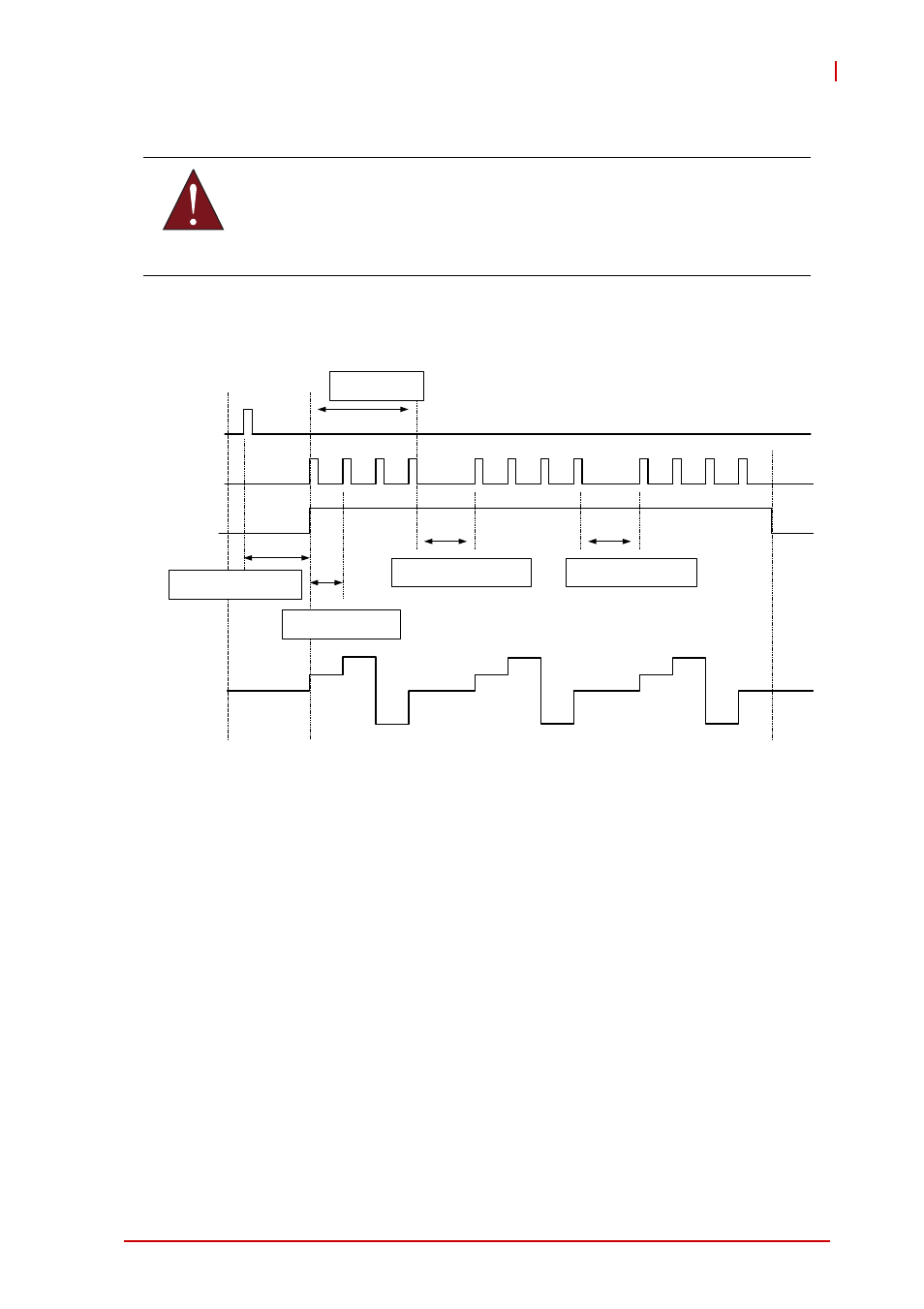
Figure 4-13: Waveform Generation Hardware Timing
Waveform Generation Triggering
The USB-1902/1903 supports flexible trigger sources for ana-
log output functionality. The trigger source can originate with
software or external digital signal in continuous waveform gen-
eration mode. Users can configure the trigger source and trig-
ger mode by software.
4.5.4
Waveform Trigger Sources
Software Triggering
This trigger mode requires no external trigger source. The trig-
ger asserts immediately following execution of the specified
function calls to begin the operation.
WARNING:
The maximum D/A update rate is 1 MHz, and the minimum
UI_counter setting is 80.
Delay until DLY1_Counter
Reaches 0
DA_Update_Interval T =
UI_Counter / Timebase
Delay until DLY2_Counter
Reaches 0
Delay until DLY2_Counter
Reaches 0
UC_Counter = 4
4 Update Count and 3 iteration count
Trigger
DAWR
WF_in_Prog
Wave