2 general purpose timer/counter, 7 basic timer/counter function, General purpose timer/counter – ADLINK USB-1903 User Manual
Page 71: Basic timer/counter function, Table 4-5: timer/counter pin definition
Operation
57
USB-1900 Series
4.6.2
General Purpose Timer/Counter
The USB-1900 Series is equipped with two general purpose timer/
counter sets featuring:
X
Count up/down controllable by hardware or software
X
Programmable counter clock source (internal clock up to 80
MHz, external clock up to 10 MHz)
X
Programmable gate selection (hardware or software con-
trol)
X
Programmable input and output signal polarities (high active
or low active)
X
Initial Count loaded from a software application
X
Current count value readable by software without affecting
circuit operation.
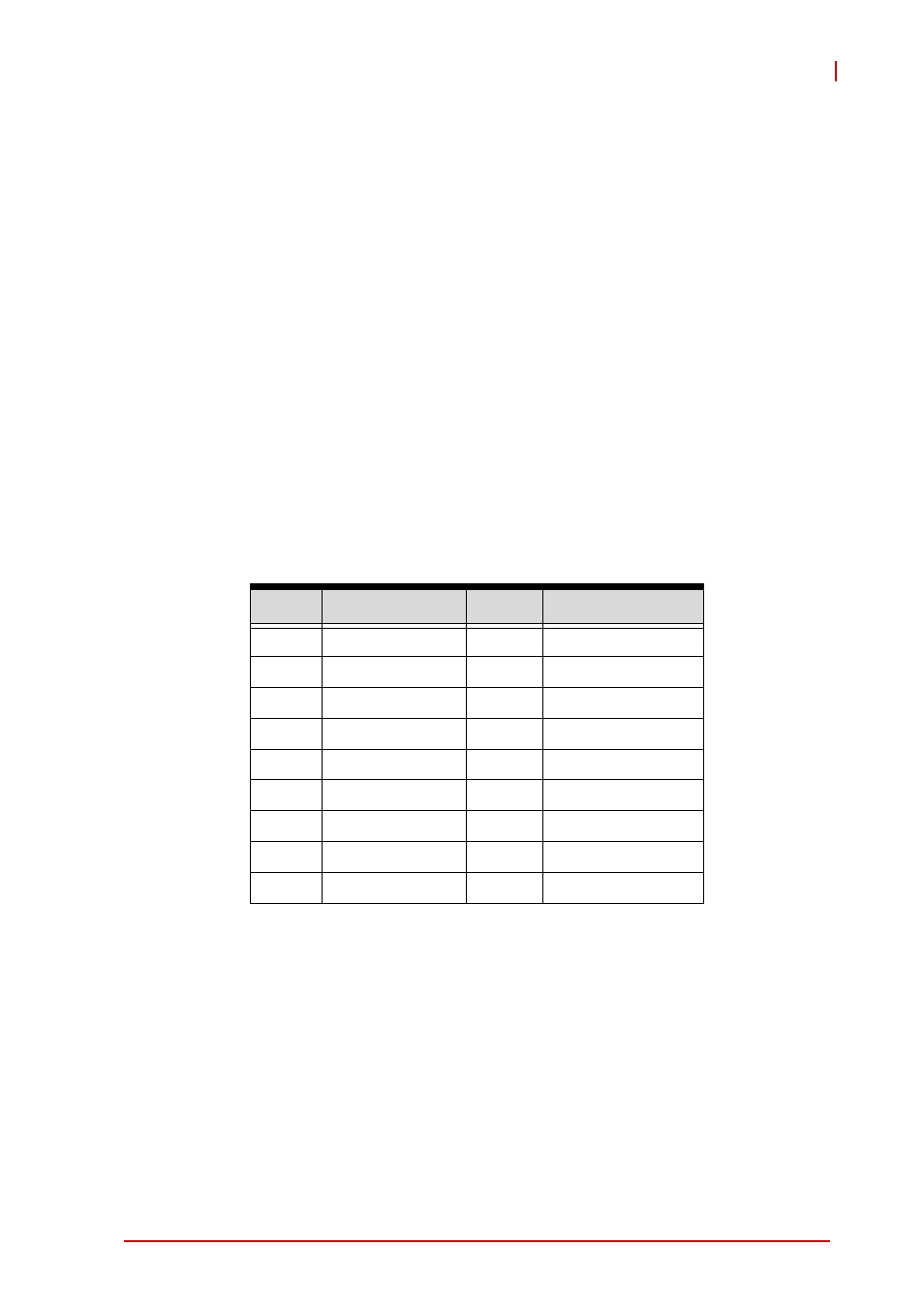
Table 4-5: Timer/Counter Pin Definition
4.7
Basic Timer/Counter Function
Each timer/counter has three inputs that can be controlled via
hardware or software. They are clock input (GPTC_CLK), gate
input (GPTC_GATE), and up/down control input (GPTC_UD). The
GPTC_CLK input provides a clock source input to the timer/coun-
ter. Active edges on the GPTC_CLK input increment or decrement
the counter. The GPTC_UD input directs the counter to count up
Pin
Function
Pin
Function
38
GPTC_AUX2
17
GPTC_OUT3
37
GPTC_GATE2
16
GPTC_OUT2
36
GPTC_UD2
15
GPTC_OUT1
35
GPTC_CLK2
14
GPTC_OUT0
34
GPTC_AUX0
13
DGND
33
GPTC_GATE0
32
GPTC_UD0
31
GPTC_CLK
30
DGND