2 mode 2: single period measurement, 3 mode 3: single pulse-width measurement, Mode 2: single period measurement – ADLINK USB-1903 User Manual
Page 73: Mode 3: single pulse-width measurement, Figure 4-19, Mode 2-single period measurement
Operation
59
USB-1900 Series
4.8.2
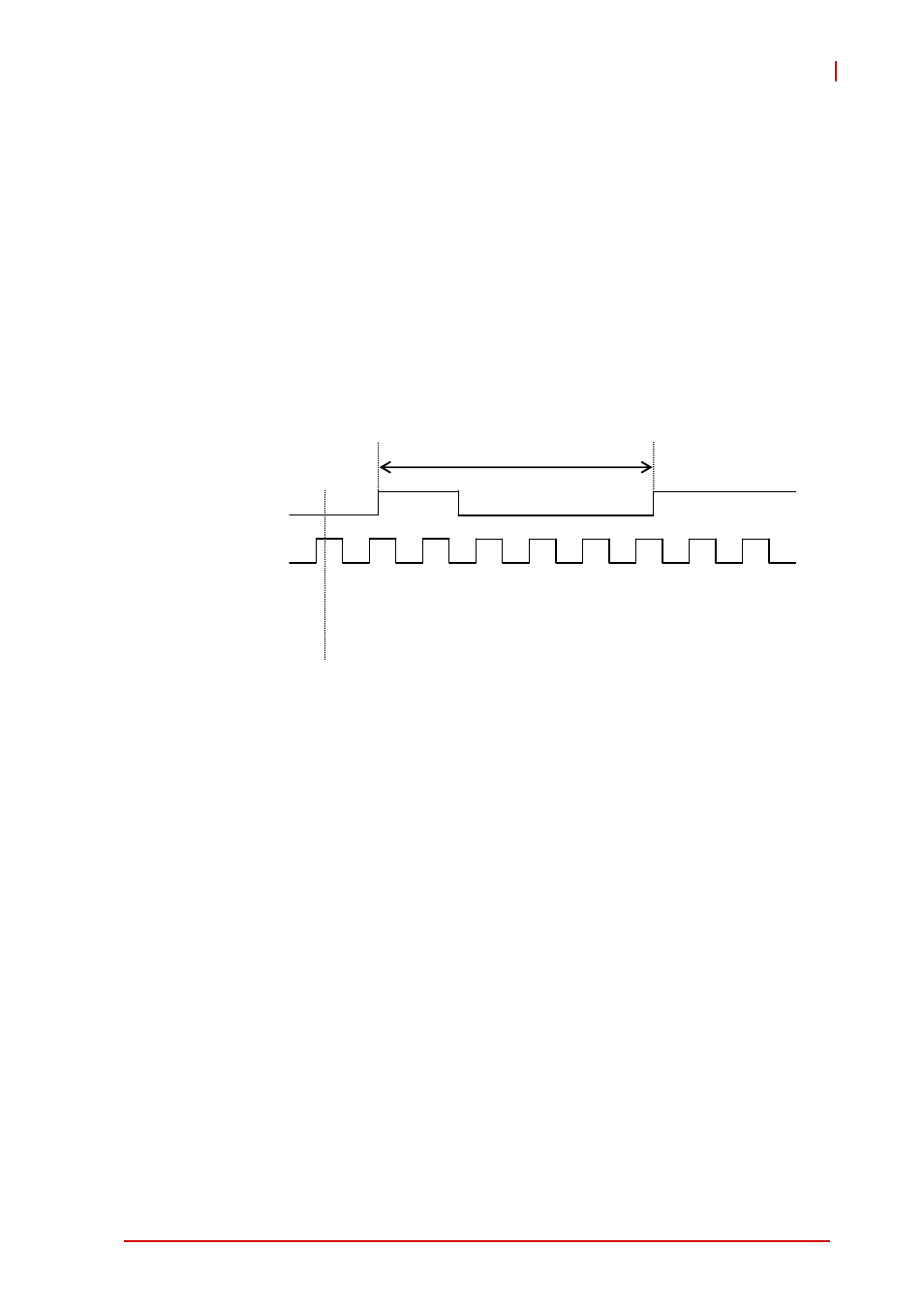
Mode 2: Single Period Measurement
The counter calculates the period of the signal on GPTC_GATE in
terms of GPTC_CLK. The initial count can be loaded from the soft-
ware application. After software start, the counter calculates the
number of active edges on GPTC_CLK between two active edges
of GPTC_GATE. After the completion of the period interval on
GPTC_GATE, GPTC_OUT outputs high and then current count
value can be read by the software application. Operation in which
initial count = 0, count-up mode is shown.
Figure 4-19: Mode 2-Single Period Measurement
4.8.3
Mode 3: Single Pulse-Width Measurement
The counter calculates the pulse-width of the signal on
GPTC_GATE in terms of GPTC_CLK. Initial count can be loaded
from the software application. After software start, the counter cal-
culates the number of active edges on GPTC_CLK when
GPTC_GATE is in its active state.
After the completion of the pulse-width interval on GPTC_GATE,
GPTC_OUT outputs high and current count value can be read by
the software application. Operation in which initial count = 0,
count-up mode is shown.
0
0
1
2
3
4
5
5
5
Gate
CLK
Count value
Software start