Cutting line head configuration, Pre-installation, Installing the dual une head (see fig. 6 & 7 – Sears 358.79828 User Manual
Page 8: Asser^/ibly, Warning
Attention! The text in this document has been recognized automatically. To view the original document, you can use the "Original mode".
ASSEr^/iBLY
CUTTING LINE HEAD
CONFIGURATION
Brush and Saw Blade Configurations follow this section.
WARNING:
THE LINE LIMITER IS SHARP AND CAN
CUT YOU. BE SURE TO WEAR GLOVES
WHIL£ WORKING WITH THE LINE UMITER.
THE
PLASTIC
UNE
TRIMMER
SHIELD
MUST BE PROPERLY INSTALLED FOR ALL
UNE
TRIMMER
USAGE.
THE
PLASTIC
UNE TRIMMER SHIELD PROVIDES PAR
TIAL PROTECTION FROM THE RISK OF
THROWN OBJECTS TO THE OPERATOR
AND OTHERS,
_____
INSTALLING UNE LnSIlTERjONTa PLASTIC
UNE TRIMMER SHIELD (See Fig. 4)
• Position Hn& limiter onto the plastic fine trimmer shield.
IMPORTANT; ALTHOUGH SCREW HOLES EXIST ON
BOTH EDGES OF THE FUSTIC UNE TRIMMER
SHIELD, MAKE SURE YOU INSTALL THE UNE UM-
ITER ON THE SIDE SHOWN IN THE ILLUSTRATION.
• Secure line limiter to the plastic line trimmer shield using
the two mounting sc/ews, lock washers, and huts found
in the loose parts bag using a phllUps screwdriver
8mm wrench.
• Tighten securely.___________________
Nuts
Lock
Washers
Plastic Line
Trimmer Shield
Une Limiter
Line Limiter parts are
located in a bag at
tached to the Plastic
Une Trimmer Shield.
'If*—Mounting ,
Screws-
Rgure 4
PRE-INSTALLATION
If the metal blade shield is installed on the unit, you must
first remove thenuf, support flange, blade, and metal blade
shield as follows before installing the plastic line trimmer
shield and dual lirre cutting head.
• Clip blade transport/storage cover over the blade.
(Refer to figure 9)
• To remove blade (See Figures 11 or14), place locking pin
through the geartjox and driving disk to prevent the arbor
shaft from turning and remove the blade nut fay turning
clockwise with blade nut/spark plug wrench. Save parts
removed for future use.
• Remove 4 screws with hex key holding the metai blade
shield. Save these 4 screws for installation of the plastic
line trimmer shield.
INSTALLING THE PLASTIC UNE TRIMMER
SHIELD (See Fig. 5)
• Place the plastic line trimmer shield oh the gearbox, and
align the four screw holes as iltusbafed,
• Place the shield support plate under the shield and
align the four screw holes.
• Secure the plastic line trimmershi^d using the 4 mount
ing screws provided in the loose parts bag.
• Tighten evenly (70 Ib-tn mimimum) using the hex key
provided in the loose parts bag.
Arbor
Shaft'
Driving
Disk
Shield Support
Plate
Plastic Une
Trimiher
Shield
Figure 5
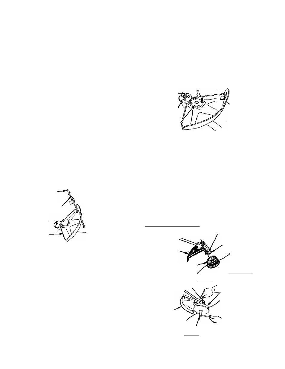
INSTALLING THE DUAL UNE HEAD
(See Fig. 6 & 7 }
Before installing the dual line head, make sure the dimng
disk is in place on the gear box.
• Rotate the hex fastener on the dual line head counter
clockwise onto the arbor shaft.
• Turn the arbor shaftto align one of the three holes in the
driving disk wfth the hole in the gearbox.
• Insert the locking pin through the gearbox and driving
disk. This will lock the driving disk, and prevent the arbor
shaft from turning while you tighten the dual line head.
• While holding the locking pin in place, tighten the dual line
head onto the arbor shaft counterclockwise using the
blade nuWspark plug wrench(15-20 Ib-ft),
Should the arbor shaft continue to turn while you are tight
ening the dual line head, re-position the /oc/dingp/nth rough
the gearbox and driving disk.
'Plastic Line
Trimmer Shield
Dual Line Head
Locking Pin Arbor Shaft
Driving Disk
Hex Fastener
(underneath)
Dual Cutting Head
Figure 6
Locking Pin
Plastic Line
Trimmer Shield
Install Counterclockwise
Blade Nut/Spark Plug
Wrench_______
Figure 7
Remove Clockwise
-8