Saw blade configuration, Pre-installation, Instalung the saw blade (see fig. 12,13, & 14 ) – Sears 358.79828 User Manual
Page 10: Checklist, Assembly, Danger
Attention! The text in this document has been recognized automatically. To view the original document, you can use the "Original mode".
ASSEMBLY
SAW BLADE CONFIGURATION
Cutting Line Head and Bnish Tri-Blade configurations are
jocated before this section.
A
DANGER:
THE METAL BLADE SHIELD MUST BE
PROPERLY
¡NSTALLED
ON
THE
UNIT
ANYTIME THE UNIT IS USED WITH THE
BUDE. THE FORWARD TIP ON THE MET
AL BLADE SHIELD HELPS TO REDUCE
THE OCCURRENCE OF BLADE THRUST
WHICH CAN CAUSE SERIOUS INJURY
SUCH AS AMPUTATION TO THE OPERA
TOR OR BYSTANDERS.
THE BLADES ARBSHARP AND CANCUTi
YOU. BE SURETmVEAR GLOXfEBWHILE
WORKING WITH BLADES. ’ ........... ........ ^
PRE-INSTALLATION
If the plastic line trimmer shield is installed on the unit, you
must first remove the dual line cutting head before instal
ling the blade, support flange, nut and metal blade shield.
• To remove (See Figure ?), place locking pin through the
geartsox and driving disk to prevent the arbor shaft from
turning and remove tiie dual line head by turning clock
wise with blade nutfepark plug wrench. Save parts re
moved for future use.
• Remove 4 screws with hex key holding the plastic line
trimmer shield. Save these 4 screws for installation of
the metal blade shield.
• Go to “Installing The Metal Blade Shield" before proceed
ing.
if you have already configured your unit for brush tn-blade
use, you have already installed the metal blade shield and
should remove the brush tri-blade.
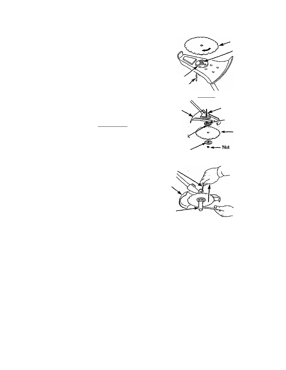
INSTALUNG THE SAW BLADE
(See Fig. 12,13, & 14 )
NOTC: The blades infigures T2-=14 i^e shown without hie
blade transport'storage cover for clarity.
Before installing the blade, make sure the driving disk is\n
place on the gear box.
IMPORTANT: WHEN INSTALLING THE SAW BLADE,
THE ARROW ON BLADE SHOULD POINT IN THE
DIRECTION INDICATED.
• Place saw blade onto support flange making sure frie
hole in the center of the blade is fitted around the raised
center step on the support flange.
• Place support flange and blade onto arbor shaft The
blade should not move from side to side.
• Insert locking pin through the gearbox and driving disk.
This will lock the dnving disk and prevent the arbor shaft
from turning while you tighten the nuf,
• Begin threading the rruf counterclockwise onto the end of
the arbor shaft, which is a left-hand thread. To tighten,
turn counterclockwise; to loosen, turn clockwise.
• While holding lodcing pin \n place, tighten the nut on the
arbor s/rari counterclockwise using the blade nut/spark
plug wrBnc/i(20-35 Ib-ft).
Driving Disk
Locking Pin
Saw Blade
Arbor Shaft
Figure 12
Metal Blade
Shield
Driving Disi
Support Flange
Locking Pin
Arbor Shaft
Saw Blade
Figure 13
Locking Pin
Metal Blade
Shield
Blade Nut/
Spark Plug.
Wrench
Install Counterclockwise
Remove Clockwise
Saw Blade
Figure 14
CHECKLIST
• Check all fasteners. Make sure they are tight and there
are no loose parts.
• Check to make sure the Throttle Cable is positioned and
clipped to the Brushcutter handlebar.
■ Check the Une Limiter. Make sure the Line Limiteris cor
rectly fastened to the plastic line trimmer shield, with the
long leg of the Line Lrm/fer pointing toward ft^center of
the shield,
• Make sure the blade is secure.
• Turn the blade by hand. If frie blade binds against the
shield or wobbles, the blade is not centered. Reinstall the
blade.
• Make sure the long arm of the handlebar extends to the
left of the tube and in front of the rperator.
• With the unit supported by its harness strap, adjust ban-
die angle for best comfort and balance before first use.
-10-