Sears 113.22643 User Manual
Page 6
Attention! The text in this document has been recognized automatically. To view the original document, you can use the "Original mode".
Contents
POWER TOOL WARRANTY .... .................................... 2
SAFETY iNSTRUCTIÖNS FOR
BELT OiSG SANDER ... .............................................2
MOTOR SPECIFIGATiONS AND :
:
ELECTRICAL REQÜiREMENTS................................ 5
UNPACKING A
nd
CHECKING CONTENTS
.6
;ASSEi^BLY'T.^:::;:..D
.........
:
Mounting Belt and Disc Sander
/
to Workbench
...7
Clamping Belt and Disc Sander
to Workbench
......7
■ Installing Sanding Disc and Guard
8
Installing Backstop.....................................................8
Installing Table Assembly .................................. ,:„8
Auxilliary Mounting for Vertical Sanding ........,....;l6
Squaring Table Assembly...................................... 10
Installing the Sanding Belt - Tensioning
^ and Tracking ........................................ .
.............. ...,io
GETTING TO KNOW YOUR
BELT AND DISC SANDER
On-Off Switch...................................
BASIC OPERATION.............. ...............
Bevel Sanding .................................
Positioning Belt Table ................ .
Surface Sanding on Sanding Belt
End Sanding bn the Sanding Beit
Sanding Curved Edges... ................
Sanding Small End Surfaces..........
MAINTENANCE.....................................
Lubrication.......................................
Removing Pulley Cover and
Installing Timing Belt.................
Installing Pulley Cover....................
TROUBLESHOOTING...........................
RECOMMENDED ACCESSORIES .
REPAIR PARTS....................................
.12
.13
.14
.16
.16
.17
.17
.17
.18
.19
.19
.19
.20
,21
.21
.22
unpacking and checking contents
TOOLS NEEDED
10HM
wrench
:
-1^
PHILUPS TYPE
SCREWDRIVER
:
standard
: SCREWDRIVER
COMBINATION SQUARE
SMM HEXT WRENCH
COMBINATION SOUAR
e
:;
must
be
true
:
DRAW LIGHT
line
ON
BOARD
along
this
EDGE
STRAIGHT
edge
OP: BOARD :
3(4" THICK: : THIS EDGE MUST
BE PERFECTLY STRAIGHT:
SHOULD BE NO GAP OR OVERLAP
HERE WHEN SQUARE IS FLIPPED
OVER IN DOTTED POSITION:
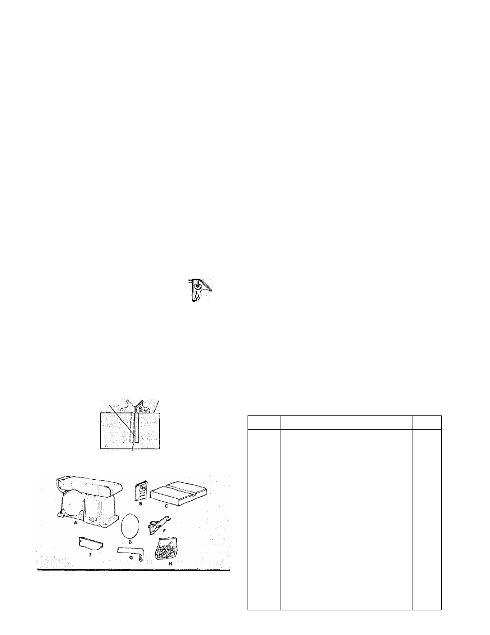
Model
113.22643 Belt and Disc Sander is shipped
cornplete in one carton.
Separate all parts from packing materials and check
each item with illustration and 'Table of Loose Parts.”
NOTE: Make certain ail items are accounted for, before
discarding any packing material.
WARNING: To avoid Injury, if any parts are missing,
do not attempt to assemble the Belt and Disc Sander,
plug In the power cord, or turn the switch on until the
missing parts are obtained and installed correctly.
WARNING:
Foryourownsafety,neverconnectplug
to power source outlet, or insert switch key until all
assembly steps are complete and until you have
read and understood the entire owners manual.
ITEM
TABLE OF LOOSE PARTS
QTY.
A
Belt and Disc Sander Assembly
1
B
Owner’s Manual
1
C
Table
1
D
Sanding Disc
1
E
Table Support
1
F
Guard Disc
1
G
Work Support
1
H
Bag Assembly
Containing the following parts;
Knob
1
Washer. 6.5 x 17.8x1.6
Screw, Pan Hd. TY "AB"
5
M4,2x 1.9-12
2
Switch Key
1
Lockwasher, Ext. M6
4
Scale Label
1
Screw, Hex Hd. M6 x 1.0-14
4
Hex “L" Wrench 6mm
1