Sears 113.22643 User Manual
Page 10
Attention! The text in this document has been recognized automatically. To view the original document, you can use the "Original mode".
AUîCILlARr MOUNTING FOR VERTICAt
:;ёАШио^
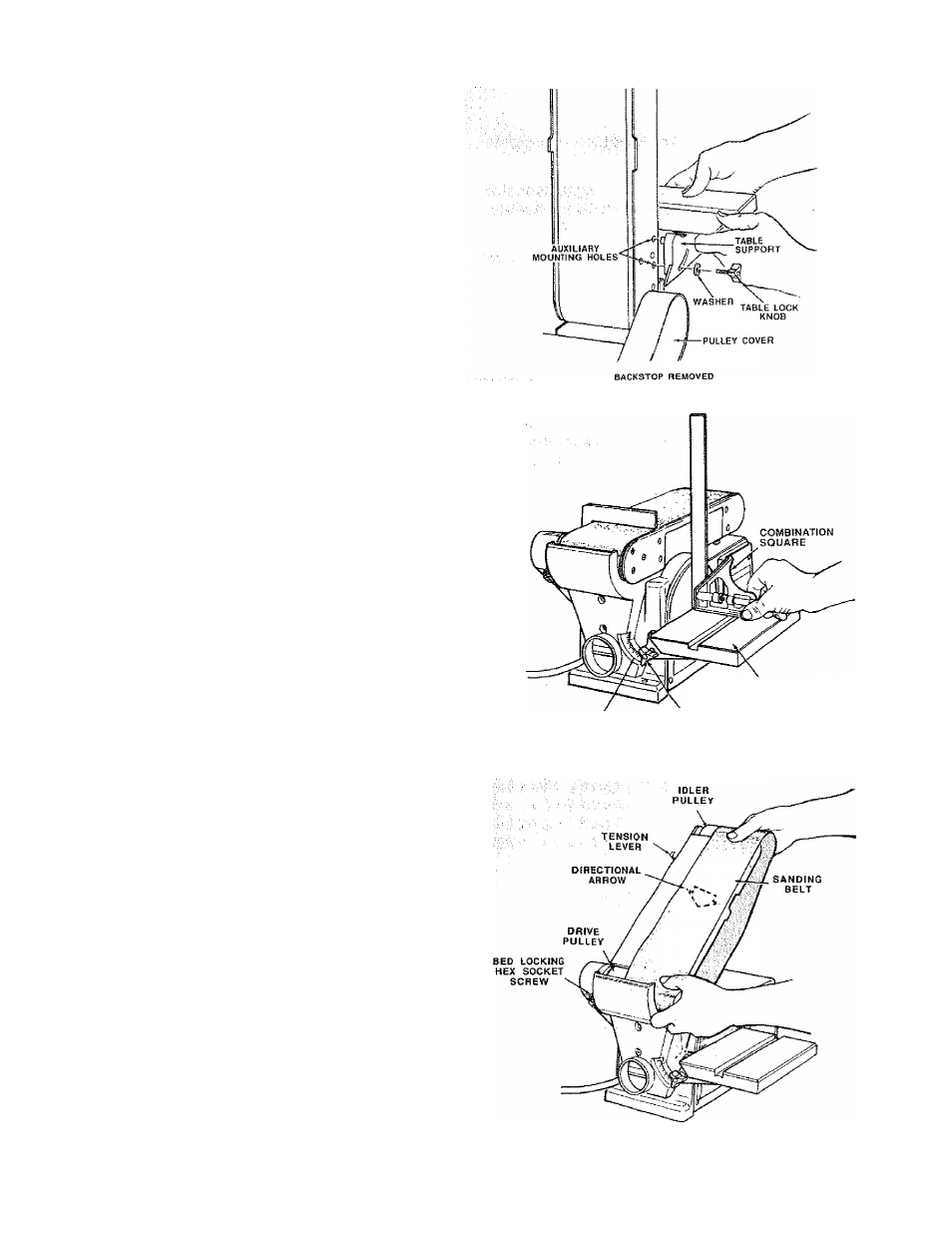
i ; Remove backstop lock bolt and remove work support.
2, Remove table assembly by rennoving table lock knob
^
- V
^ ■ ■
NOTE: Belt bed may be raised to vertical position by
loosening hex socket screw and raising bed. See
"Positioning Belt Bed" on page 16.
3. Attach table assembly to auxiliary holes in belt bed.
Make sure index pinisinthe upper hole when sanding
table is in the vertical position.
^ ^
SQUARING TABLE ASSEMBLY
WARNING: To avoid Injury from accidental start,
make sure toot is unplugged before aligning.
1. Using a combination square, check the angle of the
wo rktable with the disc.
NOTE; The combination square must be “true"- See
"Unpacking - tools Needed" section on page 6 for
checking method.
2. If the table is hot 90“ with the disc, loosen table lock
knob screw and tilt tablé;
3v Adjust worktable square to the disc and retighten
table lock knob.
:
4. Attach scale label to 6“ rnark on dust guard.
WORKTABLE
SCALE LABEL
TABLE LOCK
KNOB
INSTALLING THE SANDING BELT -
TENSIONING AND TRACKING
WARNING: To avoid injury from accidental start,
turn switch “OFF", remove key and remove plug
from power source outfet before removing or install"
ing sanding belt. To avoid Injury frofrj belt failure,
use only Sears recommended sanding belts. See
Sears catalog.
On the smooth side of the sanding belt, you will find a
“directional an-ow." The sanding belt must run in the
direction of this arrow so that the splice does not come
apart.
1. Slide tension lever to the right to release the belt
tension.
2. Place the sanding belt over the pulleys with the
directional arrow pointing as shown. Make sure the
belt is centered oh both pulleys.
10