Carrier 50BA User Manual
Page 7
Attention! The text in this document has been recognized automatically. To view the original document, you can use the "Original mode".
m
The 064 compressor hold-down bolts must be
removed. The neoprene grommets are installed
between compressor feet and special washers. Hold
down bolts are installed and tightened until there is
a slight pressure on the neoprene grommets.
Compressors have reversible oil pumps that
operate in either direction. Direction of rotation
need not be checked.
NOTE: Do not loosen bolts on 50BA008
compressor.
Water-Cooled Condenser Connections
— Con
densers have water inlet and outlet connections as
shown in Fig. 14. Recirculating systems with low-
temperature water returning to condenser may
require a water regulating valve. Units used on
waste or city water must have a regulating valve on
the inlet of each condenser and will require field
modification for separate condenser piping (except
016). See Fig. 15, 16, 17, 18, 19, 20 and 21 for
typical application and conversions. Connect regu
lating valve capillary to a back-seated liquid service
valve. Arrow on valve body must point in direction
of flow. After connecting capillary, open regulating
valve one turn from back-seated position. Adjust
valve to maintain proper condensing temperature.
Install full size gate valve and strainer in water
supply line. Valve and strainer must be accessible.
Maximum Water Side Working Pressures Are;
50BA008, 012 ................................... ISOpsig
50BA016
.................................... 550 psig
50BA024 thru 054 ................................. 150 psig*
50BA064
.................................... 250 psig
*550
psig
if
factory-installed
couplings
are
removed
and
field-
fabricated manifold is installed.
Condensate Drain
— Requires standard pipe con
nected to condensate pan nipple as shown in Table
4. Pitch downward to open drain. Provide trap
3 in. high and plugged tees for cleaning. If
required, cut hole in panel for drain line. Observe
all local sanitary codes.
Table 4 — Condensate Drain Connections (in.)
Table 5 — Recommended Line Sizes* (in.)
(Condenserless Models)
UNIT SIZE
008,
012
016,
024
028,
034,
044, 054
064
PIPE SIZE
%
1
l'4
T4
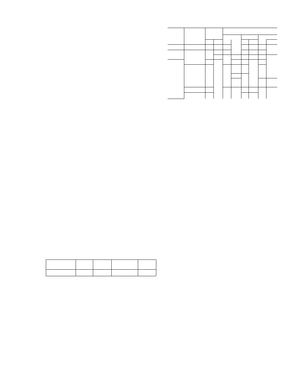
Air-Cooled Condenser Connections
— Locate con
denser not more than 60 ft above or 15 ft below
base unit. Install air-cooled condenser in accord
ance with Installation Instructions shipped with
condenser. Consult Carrier System Design Manual
for standard refrigerant piping techniques. Connec
tion location for liquid and hot gas service lines is
shown in Fig. 14. Also see Table 5. Condenserless
units are shipped with a holding charge. After
UNIT
50BB
CONN.
LENGTH OF LINE
SYSTEM
SIZESt
20
40
60 -80
L
HG
L
HG
L
HG
L
HG
008
-
’4
Ve
V
2
Ve
‘4
Ve
‘4
Vs
012
-
Vs
Ve
Ve
\
Ve
IVe
Ve
1Ve
016
~
%
IVe
Ve
T/e
V
iVs
Ve
T/s
024
Î & 2 “1
V,
Ve
Ve
Ve
Vs
IVe
Ve nv;
028
1
2
Vs
Vs
ÎVe
V
/8
Ve
V
/8
IVe
Ve
Ve
Ve
T/e
IVs
Vs
V
4
T/e
T/e
034
1 & 2
Vs
'Ve
5/
'9,
tVs
V
4
IVs
4
T/e
044
1 & 2
3
Ve
Ve
iVe
Ve
V
/8
V
/8
IVe
Ve
Ve
Ve
T/e
T/e
V
4
4
T/e
T/e
054
t,2,3
V»
IVe
V
'9,
)Vs
V4
T/e
V
4
iVe
064 ^
1 & 2
Vs
iVe
V/8
IVs^
V4
T/e
4
T/s
HG — Hot Gas Line (OD in )
L — Liquid Line (OD in )
*Using R-22.
1 Sweat connections
refrigerant connections are made, evacuate, leak
test and charge system as described in Charging
Procedure. Refer to Table 1 for unit charge. Water
regulating valve on water-cooled condenser or
condenser airflow on air-cooled condenser must be
properly set before checking system charge.
Carrier Compatible Fittings (50BB008 and 012
units only)
TUBING — Cut tubing to length with tube cutter
and remove burrs.
MECHANICAL CONNECTION - Make one con
nection at a time.
1. Mark required insertion depth on tube, 1-1/4
in. for 5/8- and 3/4-in. OD tubing.
2. Remove plug from fitting and loosen nut one
turn.
3. Position tube, remove plug and insert tube into
fitting. Bottom tube past depth gage mark.
4. Leave nuts at condenser end of tubing. Loosen
and purge one line at a time using holding
charge in base unit.
5. Tighten nuts to stop on unit fitting collar.
6. Open all service valves.
SWEAT CONNECTION
1. Clean tube and remove plug and nut from
fitting.
2. Remove O-ring from inside fitting with bent
pin. Wrap entire valve with wet rag
3. Bottom tube in fitting and solder with low-
temperature solder such as Allstate 430.
Moisture or Liquid Indicators
are located ahead of
thermal expansion valves. They must be full of
liquid refrigerant to indicate proper moisture
content. Operate system 30 minutes before deter
mining moisture content.