Table 3 — torque requirements – Carrier 50BA User Manual
Page 5
Attention! The text in this document has been recognized automatically. To view the original document, you can use the "Original mode".
WHEEL
Fig. 5 - 028 and 034
Horizontal Fan Motor
Mounting Angles
Fig. 6 — 054 and 064
Vertical Fan Motor
Mounting Angles
FAN MOTOR
50BA,BB
028,034
SUPPORT CHANNEL
50BA,BB
054,064
-MOTOR
^ MOTOR
Li^oTOR
ADJUSTING
SUPPORT
SUPPORT
SCREW
ANGLE
CHANNEL
Fig. 7 — Motor
Mounting
Fig. 8 — Assembled
Fan Motor
Adjusting Screw
2. Remove two adjusting screws; lift out motor
plate.
3. Position motor on motor plate and fasten with
fasteners provided as shown in Fig. 7.
4. Lift motor-plate assembly and slide onto
channels; be sure plate slides under lip guides.
5. Reinstall adjusting screws and adjust motor
position.
6. Fasten motor plate to channels.
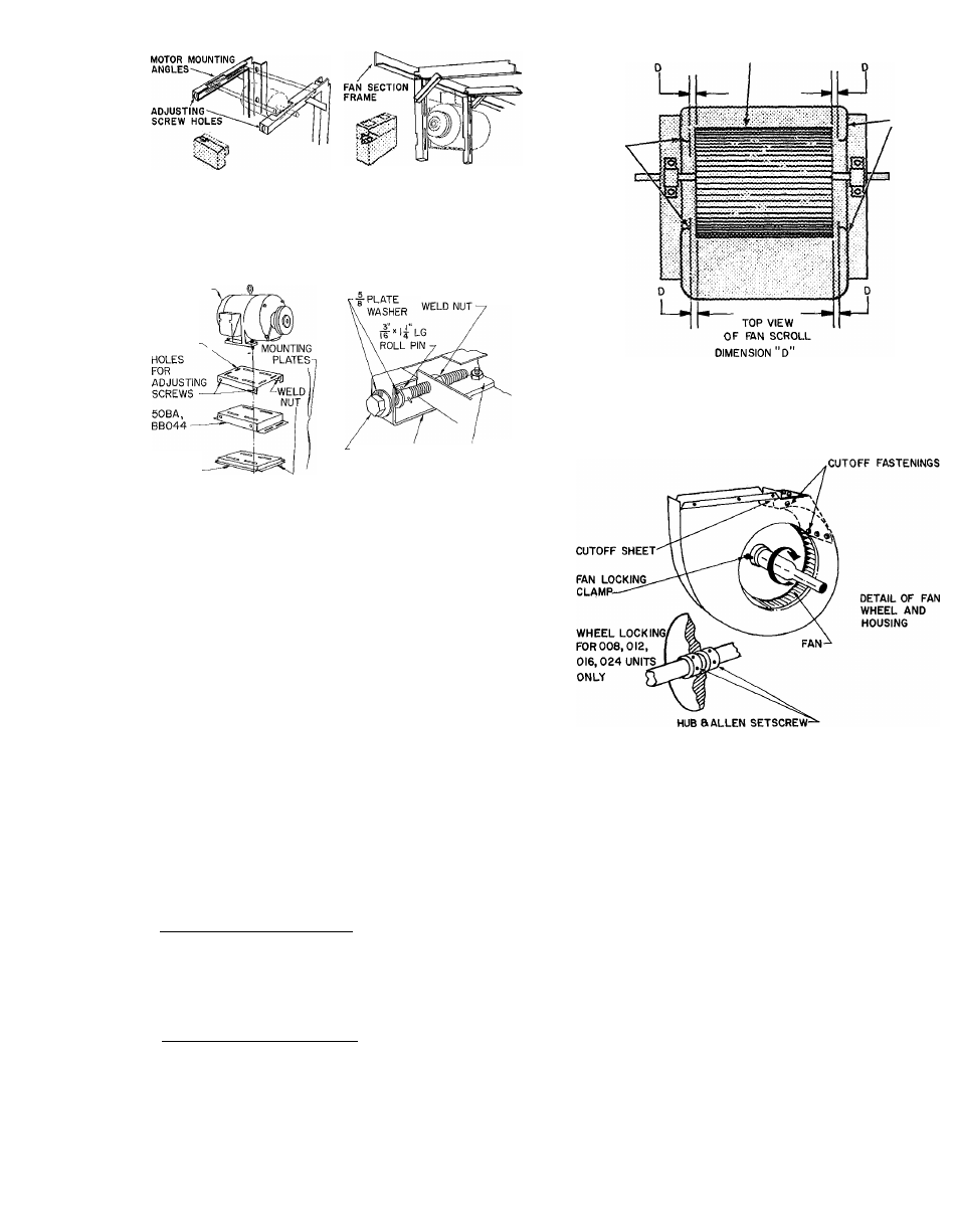
Shaft and Wheel Alignment
— On units where fan
section is shipped separately, check alignments
before mounting fan section.
HORIZONTAL WHEEL CENTERING - All
wheels must be horizontally centered between the
inside edges of their respective fan scroll venturis
(Fig. 9). To adjust individual wheels:
Units 50BA,BB008 thru 024
1. Loosen setscrews holding wheel support to
shaft (Fig. 10).
2. Center wheel by sliding horizontally (Fig. 9).
3. Retighten setscrews.
Units 5QBA,BB028 thru 064
1. Loosen fan wheel locking clamps, one on each
side of fan support (Fig. 10).
2. Center wheel by sliding horizontally (Fig. 10).
3. Re tighten locking clamp bolts using torque
indicated in Table 3.
VENTURI
7SCROLL
MUST BE EQUAL ALL AROUND
Fig. 9 — Horizontal Wheel Centering
Fig. 10 — Fan Locking Detail
- 028,034,044,054,064
Table 3 — Torque Requirements
BOLT SIZE (in.)
5/16
7/16
FAN CLAMP BOLT
RECOMMENDED TORQUE (ft - lb)
15 -
30 ^
35
CONCENTRIC ALIGNMENT - Shaft and wheels
must be concentrically centered with respect to the
venturi or air inlet of the fan housing (Fig. 11).
Units 50BA,BB008 thru 024 - Shaft bearings are
held by a “spider” support, Fig. 12. If shaft and
wheels are concentrically misaligned due to ship
ping shock, it is possible to rebend spider arms to
their original position. Spider should be replaced if
it has been extensively damaged by shipping shock.