Table 6 — electrical data, Heating coils – Carrier 50BA User Manual
Page 11
Attention! The text in this document has been recognized automatically. To view the original document, you can use the "Original mode".
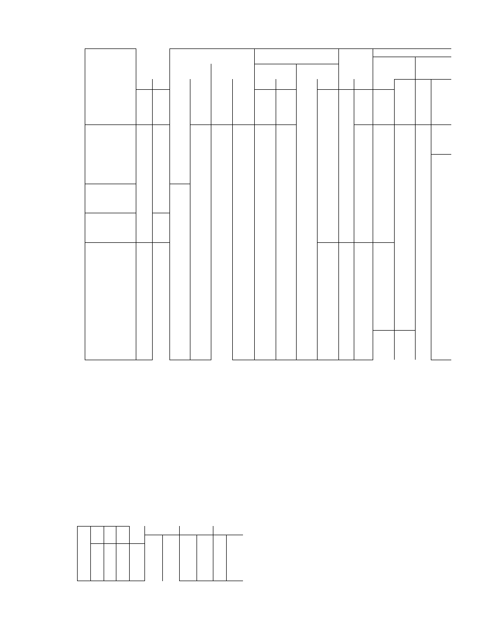
Table 6 — Electrical Data
UNIT
50BA,BB
008
012
016
024
028
#
034
044
054
064
VOLT
AGE
RANGE
COMPRESSOR NO. 1*
COMPRESSOR NO. 2*
INDOOR
FAN
MOTOR
POWER SUPPLY
Min
Max
V0LTS/PH/H2
RLA
LRA
RLA
LRA
Ckt
Amps
Fuse
Amps
Min
Max
BA
BB
BA
BB
BA
BB
BA
BB
Hp
FLA
BA
BB
BA
BB
200-3-60
180
229
-
31 3
_
137 0
—
-
-
-
1
3 45
43 2
-
7T~
208-3-60
187
229
28.6
_
134.0
_
-
-
—
1
3 45
39 0
-
60
-
230-3-60
198
254
24.0
28.3
116.0
124 0
—
-
-
-
1
3.40
33 4
39 0
50
60
46(3-3-60
414
506
12.5
14 1
58,0
62.0
—
-
-
1
1 70
17 5
19 4
25
30
575-3-60
518
6601
10.2
11 3
46.4
50.0
-
-
-
u ^
1.40
14 2
15 5
20
25
200-3-60
180
229
31.3
40 1
137.0
170 0
—
-
2
7 10
46 9
57.8
70
90
230-3-60
198
254
28 3
36 0
124.0
153.0
_
-
-
-
2
5 60
42 2
51 8
70
80
460-3-60
414
506
14.6
18 0
62.0
77.0
-
-
—
-
2
2.80
21 1
25 9
35
40
575-3-60
518
660
11.4
14.4
50 0
62.0
-
-,
-
-
2
2.30
16 6
20 7
25
35
200-3-60
"180"
"229
50.0
64,0
191.0”'
266.0
__
—
2
^7.10
70 0
87 8
80
100
230-3-60
198
254
45.0
58.0
172.0
240.0
—
—
2
6.20
63 0
79 0
70
90
460-3-60
414
506
22 1
29 0
86.0
120 0
_
-
__
2
3.10
31 0
40 0
50
50
575-3-60
518
660
17 9
23 0
69.0
96.0
-
-
-
-
2
2 50
25 0
32 0
40
35
200-3-60
180
229
36.0
^ 44.0
137 0
170 0
36 0
44,0
137 0
170 0
3
10.6
92 0
ММ5 Т
i lo'
150
230-3-60
198
254
32.0
40 0
124.0
153.0
32 0
40.0
124.0
153.0
3
9,2
81 6
99.6
100
125
460-3-60
414
506
16 0
20 0
62.0
77 0
16.0
20.0
62 0
77.0
3
4.6
40.8
49.8
50
60
575-3-60
518
660
12.9
16 0
50.0
62.0
12 9
16.0
50.0
62,0
3
3 4
32 9
40 0
45
45
200-3-60
180
229
49.3
^ 64.0
191 0
266 0
35 1~'
45.0
138.0
170 0
5
16.2
114/^
142 5
125
175
230-3-60
198
254
44.3
58.0
172.0
240.0
32.0
41 0
124.0
153 0
5
13 2
102 7
128 7
no
150
460-3-60
414
506
22.2
29.0
86.0
120.0
16.0
20.0
62.0
77 0
5
6 6
51 4
63 9
60
70
575-3-60
518
660
18.0
23.0
69.0
96.0
13 0
17 0
50.0
62 0
5
5 6
41 0
51,9
45
70
200-3-60
180
229
49 3
64.0
191.0
266 0
49.3
64.0
191.0
266 0
5
16.2
128 5
161 5
150
175
230-3-60
198
254
44.3
58.0
172.0
240.0
44,3
58 0
172.0
240.0
5
13 2
114 9
145 7
125
175
460-3-60
414
506
22.2
29.0
86.0
120 0
22 2
29.0
82,0
120 0
5
6 6
57 6
72.9
60
80
575-3-60
518
660
18.0
23.0
69.0
96.0
18 0
23 0
69 0
96 0
5
5 6
46.0
57 9
50
80
200-3-60
180
229
50.0
64.0
191.0
266.0
36.0
44,0
137 0
170.0
7/2^ 20.8
173 8
213.3
200
225
230-3-60
198
254
45.0
58.0
1 72 0
240 0
32.0
40 0
124 0
153.0
7/2 19 0
152.0
190.0
175
200
460-3-60
414
506
23.0
29 0
86.0
120 0
16.0
20 0
62 0
77 0
7/2
9 5
77 0
95.0
90
110
575-3-60
518
660
18.0
--
69.0
-
13.0
-
50.0
-
7/2
8.4
62.5
-
80
-
200-3-60
180
229
5Т.0
64.0
191.0
266.0
__
_
10
28 4
М94 7
240 2
225
250
230-3-60
198
254
45.0
58.0
172.0
240.0
-
—
-
_
10
26.0
172 0
215 0
200
225
460-3-60
414
506
23.0
29.0
86.0
120.0
—
-,
_
-
10
13 0
88.0
107.0
100
125
575-3-60
518
660
18.0
69.0
-
-
-
-
--
10
10.5
69.5
-,
80
200-3-60М
180
229
101.4
129 0
387.0
464.0
101 4
129 0
387 0
464,0
15
43.1
276 7
337.8
300
400
230-3-601
198
254
91.4
119.0
350.0
420 0
91 4
119 0
350 0
420.0
15
39 1
247.0
312 0
300
350
460-3-60t
414
506
47.2
60 0
175.0
210.0
47.2
60 0
175 0
210.0
15
19 5
125 0
156 0
150
175
575-3-60
518
660
37.2
50.0
140.0
170.0
37 2
50 0
140 0
170.0
15
15.6
99 0
128.0
110
150
FLA — .Full Load Amps
LRA — Locked Rotor Amps
RLA — Rated Load Amps
•Units 50BA.BB044 and 054 have 3 compressors. On
044 units, compressor no, 1 data applies to Systems 1
and 2, compressor no 2 data applies to System 3 On
054 units, compressor no 1 data applies to Systems 1,
2 and 3.
I'Maximum voltage range for 50BA008 is 632
¡•Part Wind
NOTES:
1
4.
Units 50BA,BB008 thru 034 are UL certified (except BA028,034 — 575 volts,
and BB024,028 and 034 - 575 volts)
Phase imbalance must not exceed 2 percent
Fan motor power wiring, circuit breakers and other electrical components are
sized
to
accommodate
special
motors
on
the
50BA,BB016,024,028
and
034
units
Wire sizing amps are sum of 125 percent of the FLA for largest motor plus 100
percent of FLA for all other motors in the unit
Maximum instantaneous current flowduring starting is the sum of the LRA for
last compressor to start plus the F LA for all other compressors in the unit
#
Table 7 — Maximum Wire Sizes for Terminal
Block (AWG or MCM)
VOLT/i
PHASE
___
208/3*
230/3
460/3
575/3
UNIT 50BA,BB
008 012 016 024
028,
044
054
064
034
BA
BB
BA
BB
BA
BB
00
00
00 001 350
0000
350
350
350 350 500
00
_
—
—
—
—
—
—
_
—
00
00
00 001 350
0000
350
0000
350 350 500
00
00
00 00
00
00 0000
0000 0000 350 350
00
00
00 00
00
00
-
00
-
350 350
An accessory defrost thermostat is required on
the 064 unit when low-pressure switch setting is
lowered or when liquid line low-pressure switch is
installed for intermediate or cold weather opera
tion. See installation instructions shipped with
accessory.
Heating Coils
— Accessory heating coils are avail
able for field installation. For installation, refer to
instructions shipped with accessory.
•50BA008 only
•|350 MCM on BB units only