Indoor air fan adjustment – Carrier 50BA User Manual
Page 14
Attention! The text in this document has been recognized automatically. To view the original document, you can use the "Original mode".
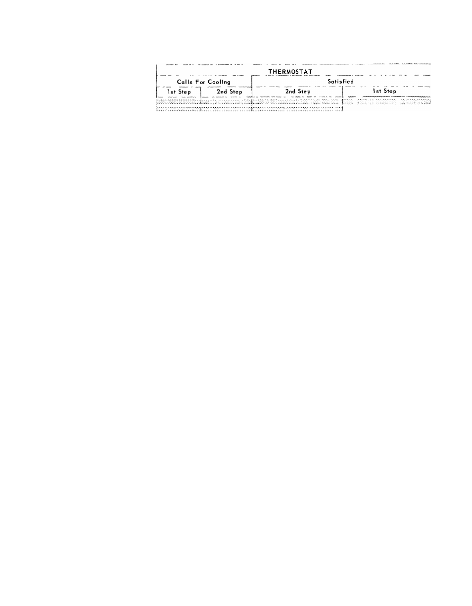
Table 10 — Sequence of Operation with Two-Step Thermostat (016 — 064)
POWER TO CONTROL CIRCUIT AND UNIT SELECTOR SWITCH ON COOL
UNIT
50BA,BB
All
Unit
Sizest
044
&
054
All
Unit
Sizest
024
028
034
044
054
064t
BB064
COMPONENT
Evaporator
Fan
Cooling Tower* *
**
Pump Motor*
15
Crankcase Heater #3*
| 15
Timer Motor #3
Compressor #3
|
Air-Cooled Cond #2* TC-C:.
(#1
on 016)
Crankcase Heater #2*
(#1
on 016)
Timer Motor #2
(#1
on 016)
Compressor #2
(#1
on 016)
Cap Cont Solenoid
(on 064 on ly)
Liquid Line Solenoid
(on 016 on ly)
Air-Cooled Cond #1*
Crankcase Heater #1 *
I’.
Timer Motor #1
Compressor #1
4 min 45
n 40 sec
4 min 45 sec
15
4 min 45 sec
Liq Line Solenoid #2
Pumpout Relay #2
Crankcase Heater #2
Ti mer Motor #2
Compressor #2
Cap. Cont Solenoid
Low Pressure Sw #2
Liq Line Solenoid #1
Pumpout Relay #1
Crankcase Heater #1
Timer
Motor
#1
Compressor
#1
Low Pressure Sw #1
1 5 sec
4 min 45 sec
30 sec
15
4 min 45 sec
30 :
yC:-; Components energized
*When used
tExcept 50BB064
$19 sec (044, 054 only)
**6 min 5 sec (044, 054 only)
NOTES
1
If compressor operation is interrupted by protective devices or a
power failure, timer motor will run 4 min 45 sec (or 6 min 5 sec)
before above cycle can be repeated
2
When
liquid
line
solenoid
(016)
or
capacity
control
solenoid
(064) is energized, it allows refrigerant to flow to complete coil
L
Indoor Air Fan Adjustment
TO CHANGE FAN SPEED (008 thru 034)
1. Shut off unit power supply.
2. Loosen fan belt by loosening fan motor from
mounting bracket. Do not loosen fan motor
mounting bracket from unit.
3. Loosen movable pulley flange setscrew (Fig.
24).
14
4. Screw movable flange toward fixed flange to
increase fan speed and away from fixed flange
to decrease speed using values shown in Table
1. Increasing fan speed increases load on motor.
Do not exceed maximum allowable fan speed
(Table 1) or motor full load amps indicated on
motor nameplate and Table 6.
5. Set movable flange setscrew at nearest flat of
pulley hub and tighten setscrew.