Capacity control valve (fig. 25), Service, Table 8 — factory set point (psig) – Carrier 50BA User Manual
Page 13
Attention! The text in this document has been recognized automatically. To view the original document, you can use the "Original mode".
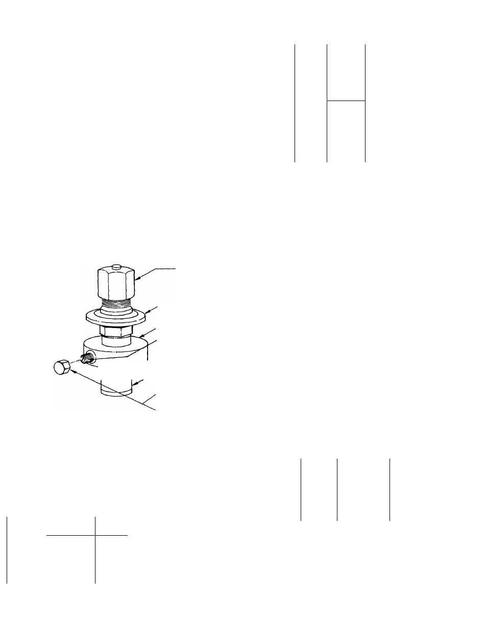
Capacity Control Valve
(Fig. 25)
CONTROL SET POINT (CYLINDER LOAD
POINT) — Adjustable from 0 psig to 85 psig.
Pressure differential between cylinder load-up
point and cylinder unload point is adjustable from
6 psig to 22 psig. (See Table 8)
TO REGULATE CONTROL SET POINT - Turn
adjustment nut clockwise to its bottom stop (with
nut in this position set point is 85 psig). Control
set point is then regulated to desired pressure by
turning adjustment nut counterclockwise. Every
full turn decreases set point by 7.5 psig. (Approxi
mately 11-1/2 turns in counterclockwise direction
will decrease set point to 0 psig.)
PRESSURE DIFFERENTIAL ADJUSTMENT -
Turn differential adjusting screw in counter
clockwise direction to its back-stop position (with
screw in this position, differential is 6 psig).
Pressure differential is set by turning adjustment
screw clockwise. Every full turn increases differ
ential by 1.6 psig. (Approximately 10 turns in
clockwise direction will increase pressure differ
ential to 22 psig.)
CONTROL SET POINT
ADJUSTMENT NUT
POWER HEAD
VALVE BODY
PRESSURE
DIFFERENTIAL
ADJUSTMENT SCREW
BYPASS PISTON RING
BYPASS PISTON
DIFFERENTIAL SCREW
SEALING CAP
REPLACE CAP TO PREVENT
REFRIGERANT LEAKAGE
Table 9 — Two-Step Thermostat Connection
for Capacity Control
COMPONENT
£NERGIZED
Compressor
Liquid line solenoid
Compressor No. 2
Compressor No 1
UNIT
THERMO
TERMINAL
50BA,BB
STEP
CONN.
016
One
T wo
2
3
_
028
034
One
T wo
3
2
044
One
3 and 5
054
T wo
2
One
3 and 6
064
T wo
2
Compressor No 2 and 3
Compressor No 1
Capacity control solenoid
va ive and I iquid ! ine
solenoid valve No. 2*
and compressor No 2
Liquid line solenoid No ]*
and compressor No ]
*BB units only
Fig. 25 — Capacity Control Valve
SERVICE
Pressure Relief Devices (Frangible Disc)
— Installed
on each condenser to 5 OB A water-cooled units at a
setting of 385 ± 5 percent psig (except 064 unit).
The 50BB condenserless units are equipped with a
fusible plug type safety relief in the compressor
with a setting of 197 E or 203 E on all units.
A pressure relief valve with a setting of 385 psig
is used on the 50BA064 condenser. A pressure
relief valve on the compressor is set at 450 psig.
Crankcase Heaters (50BA008, 064, and all 50BB)
— Prevent liquid refrigerant from accumulating in
compressor crankcase during extended shutdown
periods. Resistance heater is automatically ener
gized when compressor stops. If unit has been
disconnected for an extended period, energize
heaters for 12 hours before starting compressor.
The 5 OB A units require heaters if installed in
unheated rooms.
High and Low Pressurestats
— High are located in
electrical panel; low on top of compressor except
50BA008 on suction line; 50BA,BB064, in control
box.
Time Guard® Control Circuit
provides automatic
reset protection (except circuit breaker), time
delay in starting and controlled cycling. If com
pressor shuts down for any reason, control
prevents restarting for time period as follows;
Table 8 — Factory Set Point (psig)
A
UNIT
50BA,BB
ACTION
•
012
Load
Unload
016
Load
Unload
I
064
Load
Unload
UNLOADER
NO. 1
69’“
_ 58_______
69
58
77"''■
58
UNLOADER
NO. 2
74
55
UNIT
50BA,BB
044,054
~M4,028,
034,064
- — — — '—
CIRCUIT
NO.
A
FULL CYCLE
MINUTES
2
1 and 3
5
..........
T'
6.4~
2
5
___ __
В
____ _____
DELAYED START
SECONDS
19'
(5
___
.......... 19"
15
Under normal thermostat cycling, time delay
between compressor starts is shown in B. The 008,
012, and 016 units have a 5-minute cycle with a
15-second delayed start. See Table 10 for 016 thru
064 units sequence of operation. Table is useful in
troubleshooting