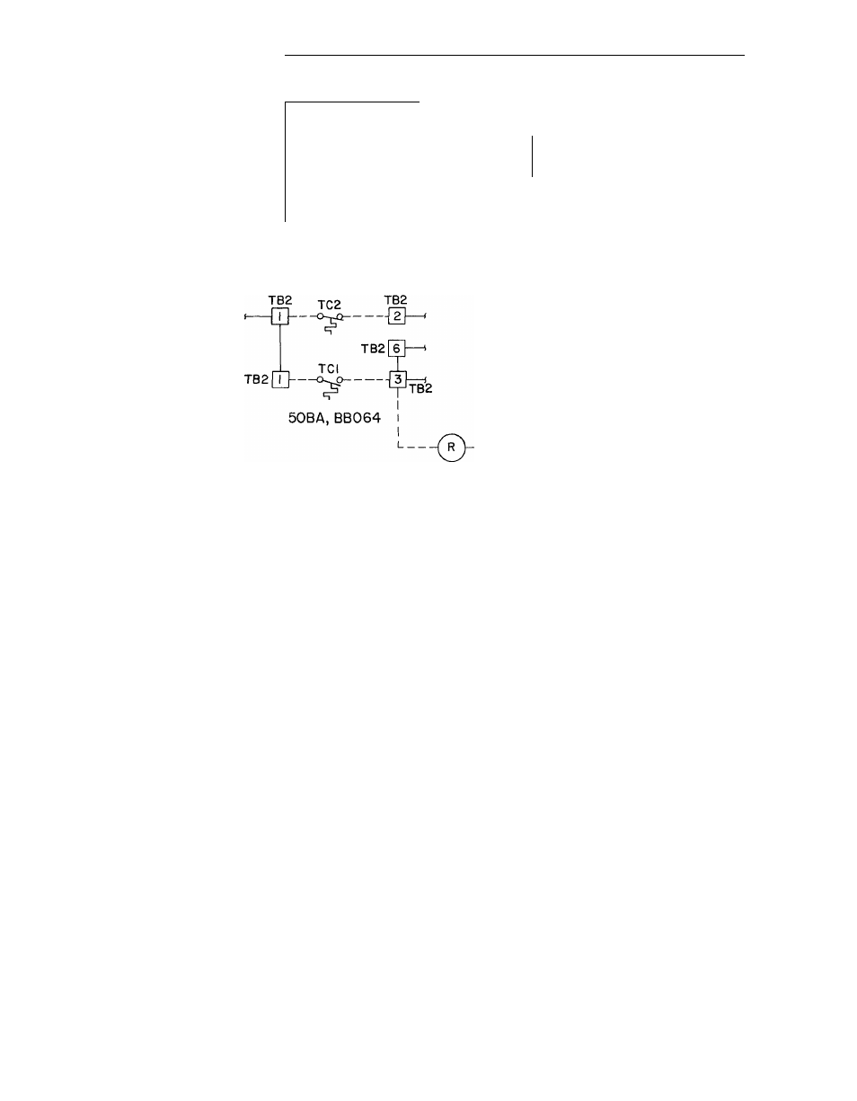
Fig. 24 — field control power connections, Start-up – Carrier 50BA User Manual
Page 12
Attention! The text in this document has been recognized automatically. To view the original document, you can use the "Original mode".
TB2
-Wl
¿
—
f —1
1
i —'
TB2 4____ ,
r—--¿H
-o^p----- > --- Î
r
u ^
1
$
1 1 TI
j
1
3 —<
1
1 TI ,
----'
T2 r-i 1
<3^^----
\I}-y
' r
L ^---------- j 6 1---
i
0
L---- -IÂ2
[IJ—i
50BB008, 50BA, BB0I2 50BA, BB0I6
--------
50BA, BB024
r
I T3
1
Tl
p-i
1^]------ (
50BA,BB044,054
IFC
R
— Condenser Fan Relay, 50BB; Pump Relay, 50BA
J
— Jumper
T or TC —
Thermostat
TB
— Terminal Board
NOTE
Condenser Fan Relay shipped with 50BB008, 012, 016 and 024 units
Fig. 24 — Field Control Power Connections
50BA, BB028, 034
START-UP
1. Thoroughly clean and inspect the unit.
2. Turn circuit breakers ON with selector switch
OFF. Leave in this position for 24 hours,
if unit is equipped with crankcase heaters (on
50BA008 and 064 units and all sizes of 50BB
units).
3. Turn selector switch to COOL. Wait at least 5
or 6 minutes for unit to start due to Time
Guard® circuit.
4. Set thermostat to proper temperature.
Service Valves
— Open discharge and suction
shutoff valves on compressor and liquid shutoff
valves before operating unit.
Liquid shutoff valves are accessible from front
or rear of unit (rear only on 064). Valve must be
back-seated (counterclockwise) to be open. After
opening valves replace caps and tighten to prevent
leakage.
Shutting Down Unit
1. Drain water from condenser and all water piping
if unit is exposed to freezing temperatures.
2. A noncorrosive antifreeze should be added to
any residual water in system.
3. Turn selector switch to OFF and turn circuit
breakers OFF.
4. If unit is to be used for winter heating, leave
circuit breakers ON. Set selector switch to FAN
and turn cooling thermostat OFF.
#
12