Self tapp«« gcsews ccilsbxnati – Carrier 50BA User Manual
Page 4
Attention! The text in this document has been recognized automatically. To view the original document, you can use the "Original mode".
MOTOR MOUNTING
BRACKETS (INSTALL
AFTER MOUNTING
FAN SECTION)
REAR HORIZONTAL FAN
AND VERTICAL FAN
DISCHARGE. 50BA.B8
028,034, D44,054
AND 064
FAN SECTION
FILTER SECTION
NO MOTOR MOUNTING
BRACKET USED WITH
044 SIZE UNIT
THREE FANS ON 054 AND
064 UNITS
REAR PANEL FAN SECTION
self
TAPP««
Gcsews
cciLSBxnati
TOPBSAft
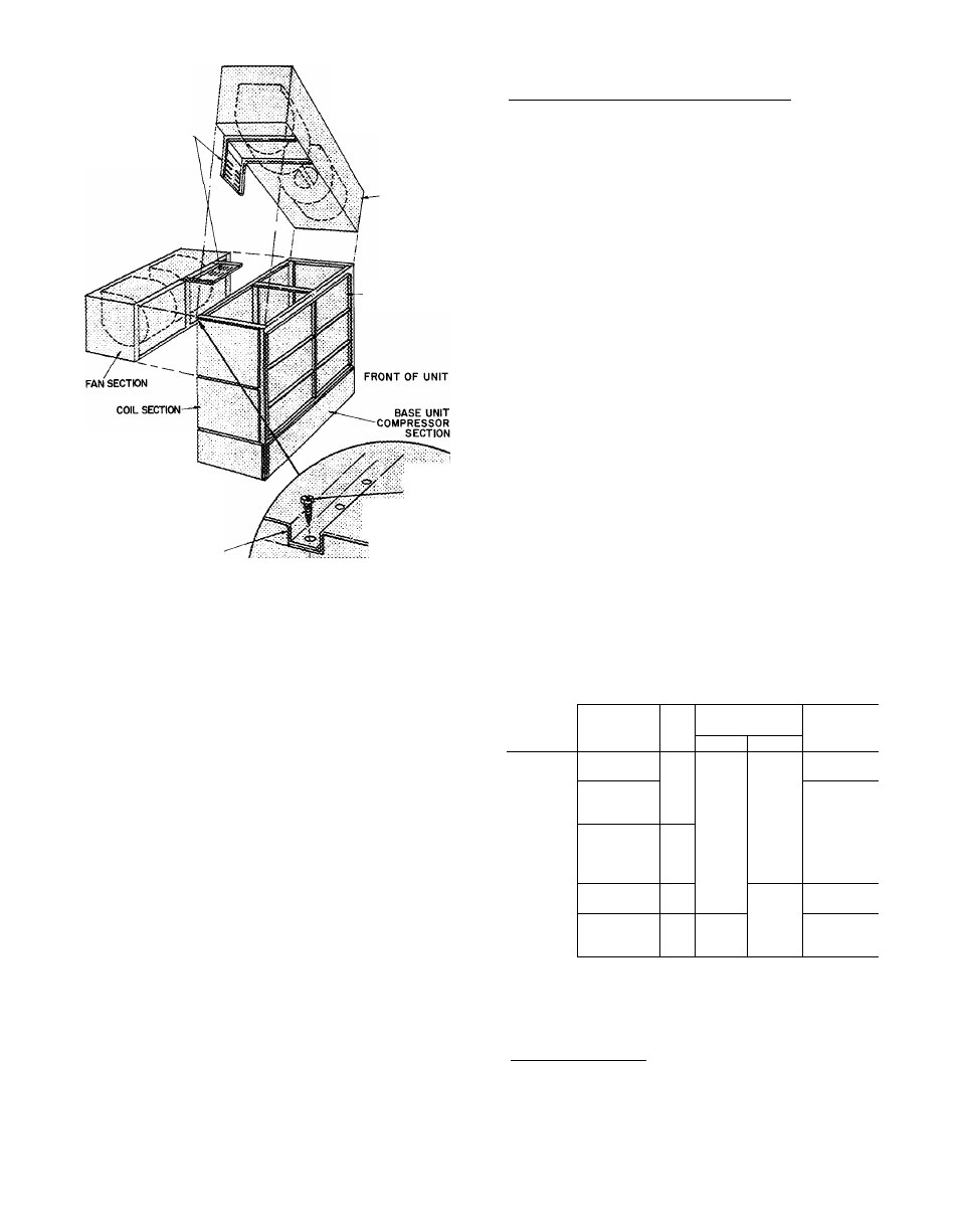
Fig. 4 — Fan Mounting
FAN MOTOR MOUNTING
Units 50BA,BB028, 034, 054 and 064 — Motor,
motor mounting assembly, drive package and
fasteners shipped separate from unit. Install items
after fan section is in place on coil section. See
Tables 1 and 2.
NOTE: Before installing motor or motor
mounts in 028, 034, 054, and 064 units place
plywood over evaporator coil to prevent
damage.
To install motor;
1. Fasten motor mounting angle bracket to fan
section. Use Fig. 3 or 4 as a position reference
and Fig. 5 and 6 as a guide. Be sure lip of angle
brackets are around fan section frame and that
motor mounting plate slots face each other.
2. Position motor on motor plate and fasten with
fasteners provided; use Fig. 7 as a guide.
3. Lift motor-plate assembly and slide into motor
mounting angles as shown in Fig. 5. Plate fits in
angle slots. On vertical mounts, the motor-
frame assembly may be lowered to bottom of
support angle channels.
4. Assemble and install motor adjusting screws as
shown in Fig. 8. Drive roll pins into screws to
prevent screws from backing out while adjust
ing motor position. On 50BA,BB054 and 064
units, the adjusting screws engage the motor
mounting plate.
5. Adjust motor position. Fasten motor mounting
plate to mounting angles.
2 Lift and position fan section on coil section,
Fig. 4.
3. a. Fasten fan section frame to coil section
frame with provided fasteners,
b. Reposition and fasten upper filter frame (on
028 and 034 only).
4. Install (see note regarding 044 size);
a. Motor mounting frame angles.
b. Motor on motor-plate assembly.
c. Motor-plate assembly into frame angles.
d. Other drive package components.
NOTE. Motor mounting plate and channels are
factory installed within fan section on 044 size
units. No angle frame plates or fasteners nec
essary. In this position motor will be on right
side of unit.
5. Adjust:
a. Fan wheel alignment.
b. Shaft alignment.
c. Pulleys
d. Fan belts
6. Replace and fasten:
a. Rear coil section panels, front and rear fan
section panels.
b. All end panels after adjustments.
Table 2 — Alternate Fan Motors and Drives
UNIT
SOBA.BB
NEMA
CENTER LINE
FAN
FRAME
HP
DISTANCE (in.)
SHAFT
SIZE*
Max
Min
DIAM (in.)
008,012
184,56,1451
182T,213
2
3
10.2
10.2
6 8
6.8
V
74
184,56,1451
2
11.8
9 4
016,024
213,182T
3
11 8
8.4
1
184T,215
5
11.8
8 4
1827,213
3
34.4
28 8
028,034
1847,215
254U,213T
5
Th
34.4
33 3
28.8
29.8
F
/16
256U,215T
10
33.3
29 8
044
254U,213T
7/2
14.3
10.1
1
V
256U,215T
10
14.3
10 1
254U,213T
7/2
33.5
29.0
054,064
256U,215T
10
33.5
29.0
284U,254T
15
33.5
29.0
‘Range of motor sizes unit will accept
NOTE:
Motors
and
drives
other
than
those
furnished
with
unit
must be purchased locally
Units 50BA,BB044 — Shipped with motor mount
ing plate installed in fan section. See Tables 1 and
2 for motor data.
To install motor:
1.
Remove bolts holding motor plate to unit
support channels.