Fig. 22 — refrigeration circuits (016 — 064), Fig. 23 — field power wiring connections, Thermostats – Carrier 50BA User Manual
Page 10: L3---- —[i
Attention! The text in this document has been recognized automatically. To view the original document, you can use the "Original mode".
REFRIGERANT IN
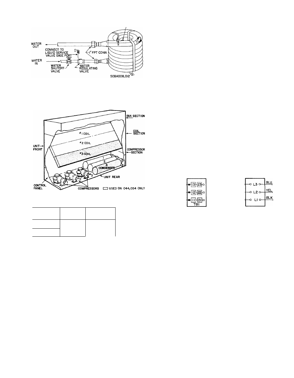
Fig. 21 — Condenser Water Piping, 50BA008,012
Refrigerant Systems
50BA,BB*
COIL NO.
COMPR NO.
016
1
1
024,028,
034,064
044,054
1, 2, 3
1, 2, 3
COND NO.*
1
1
,
2
1, 2, 3
*50BB units are condenserless
Fig. 22 — Refrigeration Circuits (016 — 064)
percent. Contact local power company for cor
rection of improper voltage or phase imbalance.
Failure of unit due to imbalance constitutes abuse
and may damage electrical components. Such
operation will invalidate any applicable warranty.
Field power may be supplied to the unit by a
feeder circuit. The branch circuit protection is
provided in the unit by manual reset circuit
breakers. The feeder circuit must be sized in
accordance with National Electrical Codes or local
codes, whichever takes precedence. The power
supply to auxiliary equipment such as air-cooled
condenser fan motors and cooling tower must be
run separately. See the electrical data table for base
unit power requirements.
The power wiring is brought into the unit thru
the conduit opening in the panel on the back of
the unit near the control panel (see Fig. 23). (On
50BA,BB064 units, power wires may be routed
thru front or back). The field power connections
are made at the terminal block inside the control
panel on the 016 thru 054 units. On the 064 unit,
the terminal block is on the back of the control
panel. Remove the metal shield for access to the
terminal block. Be sure to reinstall shield after
connecting power wiring.
FIELD
POWER
SUPPLY
FIELD
POWER
SUPPLY
50BA,BB008,0I2
50BA,BB0l6-054
TB3
-------- FIELD WIRING
-------- FACTORY WIRING
/ L3---- —[I]-
FIELD I
POWER j L2-
SUPPLY /
(
li
-----------Q}-
50BA, BB064
Fig. 23 — Field Power Wiring Connections
i
i
Service Valves (50BB)
— Teflon seat washers are
used to provide positive seal with minimum stem
torque (10 ft—lb max). Do not overtighten valve
stem. Use wet rag on valve when soldering. Midseat
valve if refrigerant has been lost. Always replace
stem cap.
Power Supply Wiring
— Unit is factory-wired for
voltage shown on nameplate. All field wiring must
comply with National Electrical Codes and local
codes.
Voltage at the unit with the compressors
operating must be within the voltage range indi
cated on unit nameplate. (Also see Table 6). On
3-phase units, voltage between phases must be
balanced within 2 percent and current within 10
Thermostats
The 50BA,BB008 and 012 model units have
thermostats factory installed with the sensing bulb
in the return air. A field-supplied thermostat must
be used on the 50BA,BB016 thru the 064 size
units (see Fig. 24 for control wiring).
Two-step thermostats are recommended fir
capacity control. Three-step thermostats may be
used on the 50BA,BB044,054 and 064 size units.
Minimum recommended rating is 125 va at 230
volts. See Table 9 for recommended connecting
sequence for the 2-step thermostats. See wiring
booklet if other type controls are used.
I
10