Carrier 39B User Manual
Page 9
Attention! The text in this document has been recognized automatically. To view the original document, you can use the "Original mode".
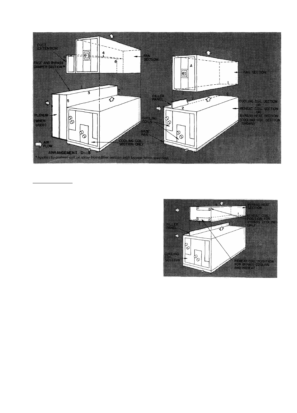
Fig. 5 - Base Unit Assembly for 39BA,BB130-140 and 39BC135,140 (Arrangement D)
Arrangement D-18
NOTE: Duct extension is shipped assembled to fan
section.
1. Remove filler panel from cooling coil section
and discard.
2. Fasten spray humidifier or preheat coil section
with bypass when specified or plenum and face
and bypass damper section to cooling coil
section per Accessory Assembly.
3.
Remove shipping skid and apply sealing
compound to flanges on air discharge side of
cooling coil section.
4. Place air intake side of fan section on top of air
discharge side of cooling coil section.
5. Fasten flanges 3 to 4 with seven 1/4-20 x 1 /2-in.
self-tapping screws and flange 4 engagement
holes.
6. Fasten flanges 5 to 6 with two 3/8-16 x 3/4-in.
hex head cap screws, lockwashers, plain
washers, and hex nuts per two flanges.
7. Tighten all screws securely.
Accessory Assembly
— Refer to Tables 1,2, and 3.
NOTE; More holes may exist than indicated. Use
only those which line up.
BYPASS HEAT SECTION (Arrangements D-31 and
D-35; sizes 135 and 140 only) - Refer to Fig. 6.
1. Remove shipping crate and apply sealing com
pound to flanges on air intake side of accessory.
2. Remove filler panel from cooling coil section
and save for fan section assembly.
3. Place air intake side of accessory on top of air
discharge side of cooling coil section.
4. Fasten flanges 1 to matching flanges of cooling
coil section with five 3/8-16 x 3/4-in. hex head
cap screws, lockwashers, plain washers, and hex
nuts per two flanges.
5. Tighten all screws securely.
Fig. 6 - Assembly of Accessory Bypass Heat Section
(Arrangements D-31, D-35; Sizes 135,140 Only)
BYPASS DUCT (Arrangement A only) — Refer to
Fig. 7.
1. Sizes 080 thru 110 —
a.
Place one endpiece on each flange 8 of
cooling coil section, with fiber glass insu
lated sides facing each other. Ensure air
intake side of bypass duct is flush with edge
of flange 9.
b.
Fasten
flange
1
to
8
with
three
1/4-20 X 1/2-in. self-tapping screws and
both flange 8 engagement holes.
c.
Fasten tabs 7 to flanges 8 with a
3/8-16 X 3/4-in. hex head cap screw, two
plain washers, and hex nut per tab.