Carrier 39B User Manual
Page 24
Attention! The text in this document has been recognized automatically. To view the original document, you can use the "Original mode".
Fan Wheel Removal
1. Remove fan shaft bearings per Fan Bearing
Replacement.
2. Remove fan shaft per Fan Shaft Removal.
3. Remove fan discharge ductwork.
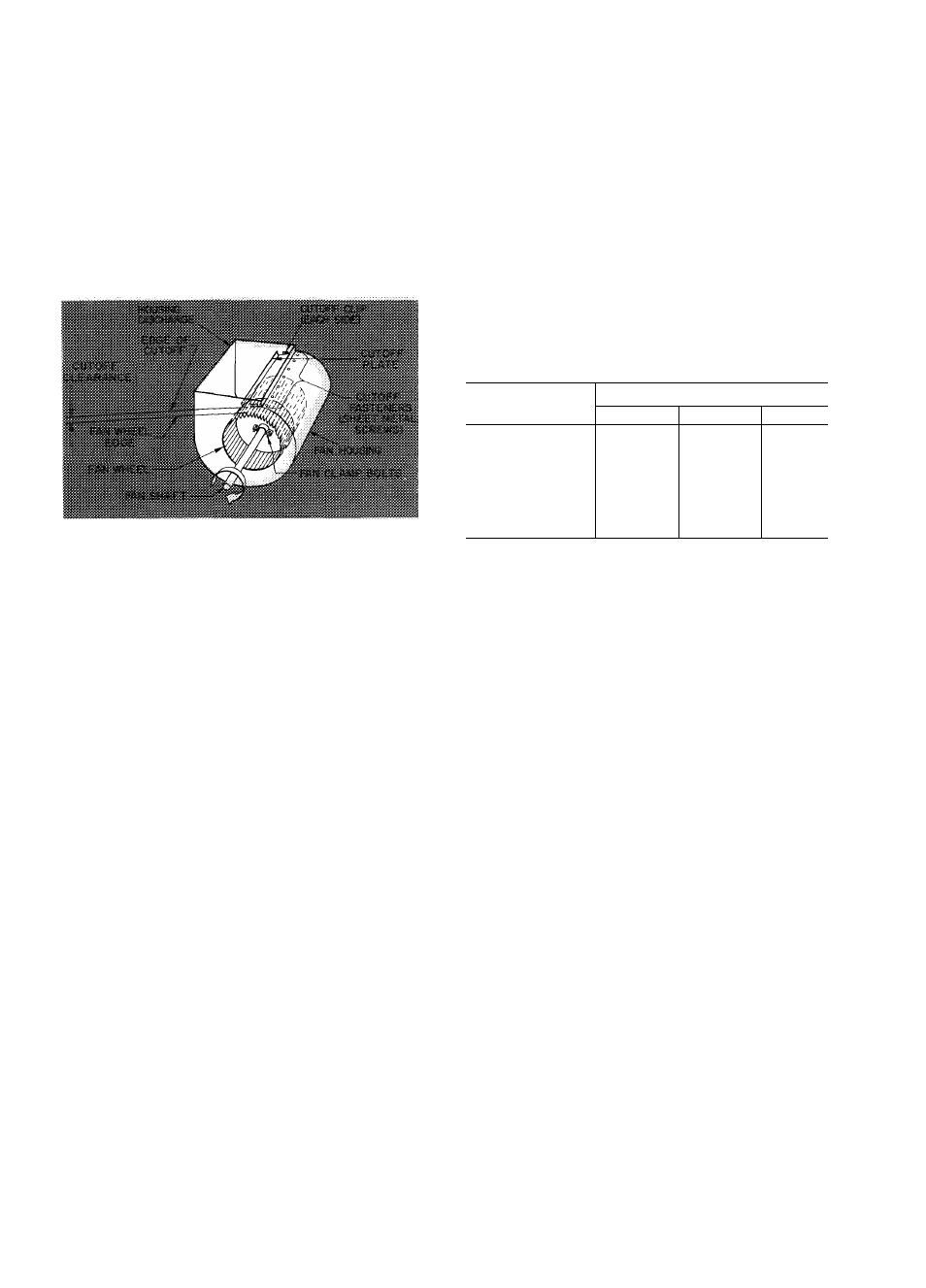
4. Remove cutoff plate per Fig. 29 and remove
fan wheel thru housing discharge.
5. Replace any damaged internal insulation.
6. Replace fan wheel in reverse order and note
following;
a. When replacing fan wheels on unit sizes
070 thru 140, ensure balancing reference
marks on wheel (normally a red line)
and clamps line up. Adjust fan clamp
torque per Fig. 2.
b. Adjust cutout clearance per Table 10. For
minor adjustment, loosen screw holding
cutoff clip to fan housing and adjust cutoff
plate. For further adjustment, loosen bear
ings and shift fan shaft.
Table 10 — 39B Cutoff Clearance (in.)
Fig, 29 — Fan Details
UNIT 39B
FAN SECTION
A
В
С
040 thru 060
1
%
-
-
070 thru 080
%
%
-
090
IMe
1Мб
-
100
thru 110
1“/з2
IVie
-
120
2У2
2
-
130
2Уд
2У
-
135 thru 140
3
2У
3
For replacement items use Carrier Specified Parts.
Manufacturer reserves the right to change any product specifications without notice.
C A R R I E R A I R C O N D I T I O N I N G C O M P A N Y • S Y R A C U S E , N E W Y O R K
Tab 9 Form 39B-1SI Supersedes 39BA041005
Printed in U.S.A.
9-71
Codes C and ME
Catalog No. 533-902