Carrier 39B User Manual
Page 21
Attention! The text in this document has been recognized automatically. To view the original document, you can use the "Original mode".
'Г
Fig. 23 — Cardboard Pattern
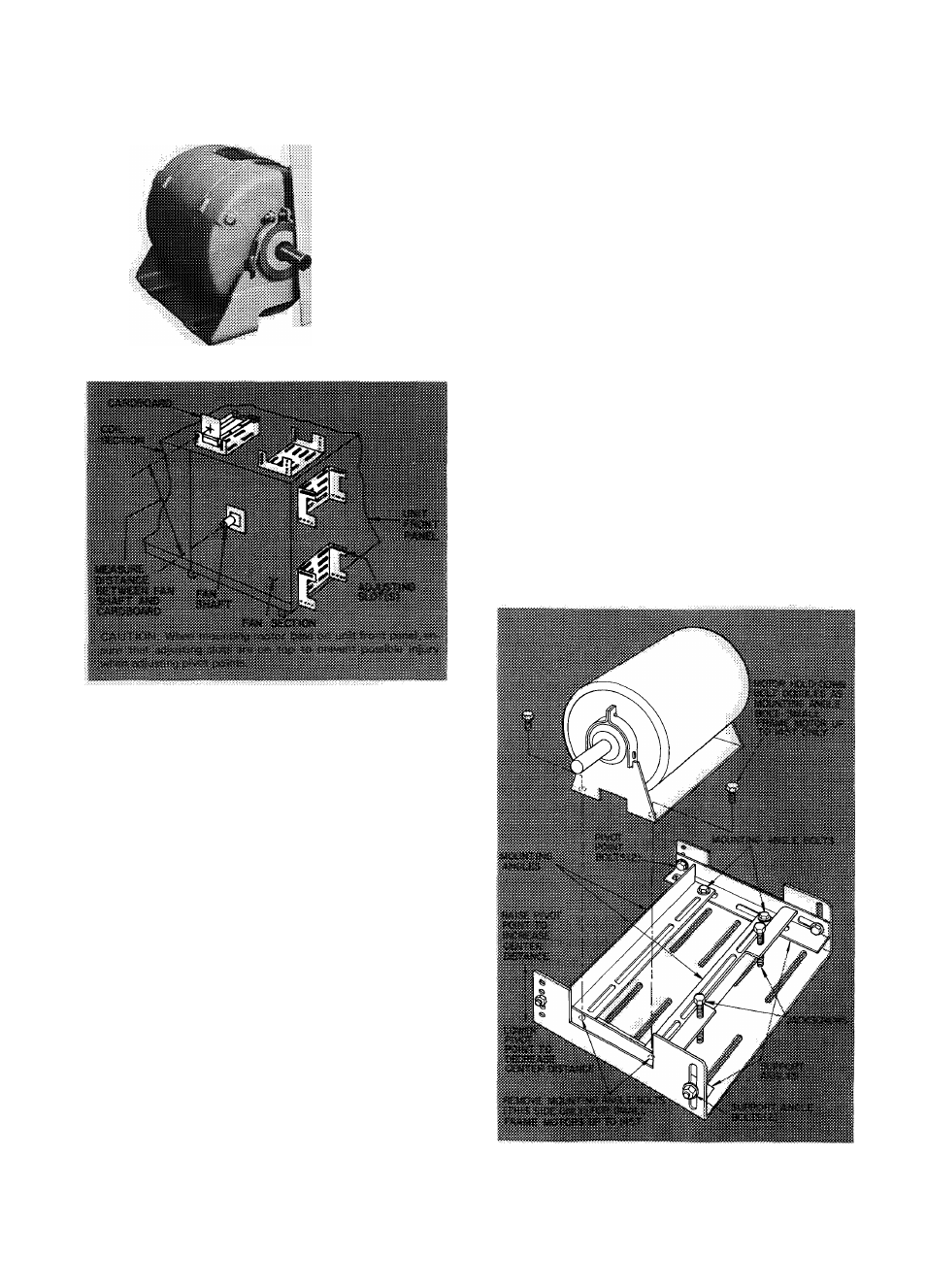
Fig. 24 — Location of Adjusting Slots
(Unit Sizes 070 thru 140)
2. Place motor on motor base with maximum
shaft overhang and install hardware from
accessory drive package; tighten securely. Posi
tion small frame motors up to 145 T per
Fig. 25. Note that hold-down bolts for small
frame motors will be smaller in diameter than
mounting angle bolts supplied in motor base,
Fig. 25.
3. Locate mounting angles so motor shaft will
hne up with center of cutout in motor base.
Make certain mounting angles are perpendic
ular to support angles and secure mounting
angle and motor hold-down bolts shown in
Fig. 25.
4. Remove protective cover and clean grease from
fan shaft with solvent.
5. Apply a light coat of grease or white lead to
fan shaft.
6. Install fan and motor sheaves with correct
angular and parallel alignment per Fig. 22.
7.
Correct alignment by repositioning motor
base.
8. Secure motor base hold-down bolts.
9. Loosen two support angle bolts per Fig. 24
and adjust belt tension by turning jackscrews.
Follow step 7 of Motor and Drive (imit
sizes 040 thru 060). A pry bar may be used to
support weight of motor.
10. Secure two support angle bolts and loosen
jackscrews.
11. Adjust motor base after mounting motor as
follows:
NOTE: If center-to-center distance was not
properly set before mounting motor, adjust
base height as follows for proper belt tension:
a.
Turn jackscrews until they contact motor
base cradle.
b.
Block up motor under mounting angle
nearest pivot points to support weight of
motor. Place lever (pry bar or 2 x 4 for
example) under same area.
c.
Loosen two support angle bolts, and
adjust jackscrews until two support angle
bolts are approximately centered in ad
justing slots.
d.
Remove two pivot point bolts, raise or
lower pivot point to obtain correct
center-to-center distance. Replace pivot
point bolts.
e.
Refer to preceding step 9 for final adjust
ment of belt tension.
f.
Secure two support angle bolts and two
pivot point bolts, and loosen jackscrews.
Fig. 25 — Small Frame Motor Mounting
(Such as 143T and 145T)
21