Carrier 39B User Manual
Page 8
Attention! The text in this document has been recognized automatically. To view the original document, you can use the "Original mode".
UNITS 39BA,BB SIZES 100 THRU 120 (Arrange
ment D, except D-17 and D-18) — Refer to Fig. 4
and Table 3.
1.
Remove shipping skids and apply sealing
compound to flanges on air discharge side of
cooling coil section.
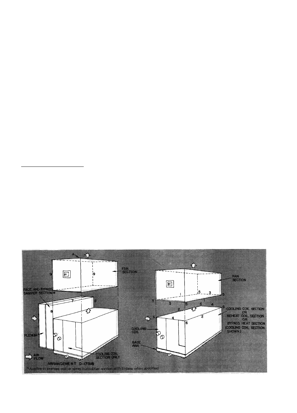
2. Place air intake side of fan section on top of air
discharge side of cooling coil section, reheat
coil section or bypass heat section.
3. Fasten flange 1 to 2 with three 3/8-16 x 3/4-in.
hex head cap screws, lockwashers per two
flanges and flange 2 weld nuts.
4. Fasten flanges 3 to 4 with one 3/8-16 x 3/4-in.
hex head cap screw, lockwasher, and hex nut
per two flanges.
5. Fasten comers 5 to 6 with one 3/8-16 x 3/4-in.
hex head cap screw, lockwasher, two plain
washers, and hex nut per two corners. Corner
holes are 11/16-in. diameter.
6. Tighten all screws securely.
Arrangements D-17 and D-18
1. Follow preceding steps 1 thru 5.
2. Fasten spray humidifier or preheat coil section
with bypass when supplied to cooling coil
section per accessory assembly.
3. Fasten flange 7 to fan section side A with three
1/4-20 X 1/2-in. self-tapping screws and side A
engagement holes.
4. Line up flanges 8 and 9 and drill two engage
ment holes in each flange 9 with a no. 3 drill.
5. Fasten flanges 8 to 9 with two 1/4-20 x 1/2-in.
self-tapping screws per two flanges.
6. Tighten all screws securely.
2
.
3.
UNITS 39BA,BB SIZES 130 THRU 140 AND
39BC SIZES 135 AND 140 (Arrangement D, ex
cept D-18) — Refer to Fig. 5 and Table 3.
NOTE: On arrangements D-31and35, sizes 135
and 140 — first fasten bypass heat section to
cooling coil section per Accessory Assembly, then
proceed with following steps;
1.
Remove shipping skid(s) and apply sealing
compound to flanges on air discharge side of
cooling coil section.
Place air intake side of fan section on top of air
discharge side of cooling coil section, reheat
coil section, or bypass heat section.
Cooling coil section —
a. Line up side A of fan section with filler
panel and drill eight engagement holes along
bottom edge of side A with a no. 3 drill.
b. Fasten filler panel to side A with eight
1/4-20 X 1/2-in. self-tapping screws.
4. Bypass heat section or reheat coil section.
a. Place filler panel, removed from cooling coil
section per Accessory Assembly, along
flange 7 of accessory section and butt
against fan section per Fig. 5.
b. Drill seven engagement holes along flange 7
with a no. 2 drill.
c. Fasten filler panel to flange 7 with seven
self-tapping screws.
d. Follow preceding steps 3a and 3b.
5. Fasten flange 1 to 2 with five 3/8-16 x 3/4-in.
hex head cap screws, lockwashers, plain
washers, and hex nuts per two flanges.
6. Tighten all screws securely.
Fig. 4 - Base Unit Assembly for 39BA,BB100-120 (Arrangement D)
8