Carrier 39B User Manual
Page 16
Attention! The text in this document has been recognized automatically. To view the original document, you can use the "Original mode".
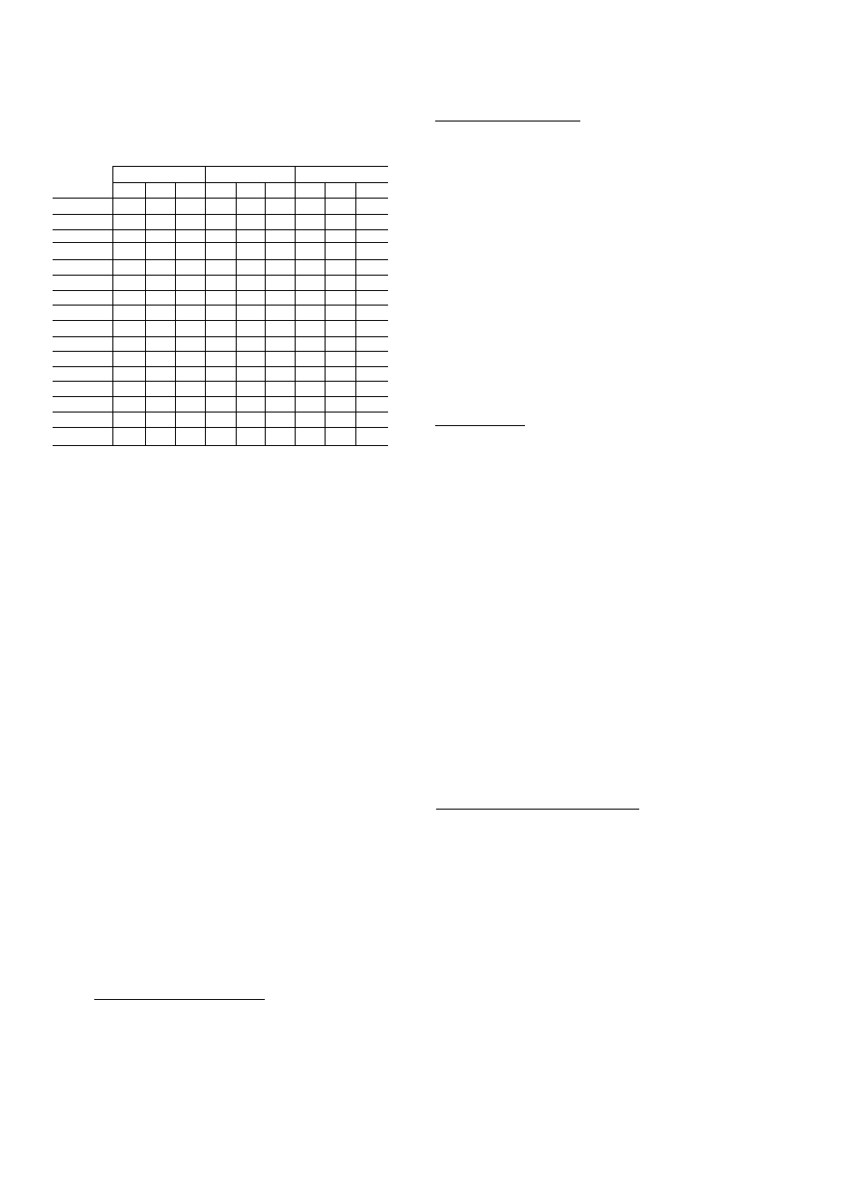
Table 6 — Refrigerant Distributor Nozzle Orifice
Capacities (Tons of Refrigeration)
NOZZLE
EVAPORATOR TEMPERATURE
ORIFICE
R-12
R-22
R-500
NUMBER
40 F 30 F 20 F
40 F 30 F 20 F
40 F 30 F 20 F
2
2.0
1.7
1.4
3.2
2.7
2.3
2.3
1.9
1.6
2-1/2
2 5
2.1
1.8
4.0
3.3
2 8
2 9
2.4
2.0
3
3.0
2.5
2.1
4.8
4.0
3.4
3.4
2.8
2.4
4
4.0
3.3
2 8
6.5
5.5
4 6
4 6
3.8
3 2
5
5.0
4.2
3.5
8.0
6 5
5.5
5.5
4.6
3 9
6
6.0
5.0
4.2
9.5
8.0
6.5
7.0
6.0
5 0
8
8.0
6.5
5.5
12 5
10.5
8.5
8.5
7.0
6.0
10
10.0
8.0
7.0
15.0
12.5
10.5
11.0
9.0
7.5
12
12.0
10.0
8.0
18.5
15.0
12 5
13.5
11.0
9.5
15
15,0
12,5
10.0
23.0
19 0
15.5
17,0
14 0
11.5
17
17.0
14.0
11 5
26.0
21.0
18.0
19 0
15.5
13 0
20
20 0
16.5
13.5
31.0
25.0
21.0
23.0
19 0
15.5
25
25 0
21 0
17.0
39.0
32.0
27 0
28 0
23 0
19.0
30
30.0
25 0
20.0
45 0
37.0
31.0
33.0
27.0
23.0
35
i
35.0
29 0
24.0
54 0
44 0
37 0
39.0
32 0
27.0
40
40 0
33 0
27.0
60 0
49.0
41 0
44.0
36 0
30.0
NOTES:
1 Orifice sizes 2-1/2, 3, 4, 5, 6 and 8 are not available for "A"
nozzles
2. Nozzle designation is stamped on nozzle; "G" indicates 7/8 in.
ODM distributor, "E" indicates 1-1/8 in. ODM distributor, "C"
indicates 1-3/8 in, ODM distributor, "A" indicates 1-5/8 in.
ODM distributor. Therefore, only the nozzles having the same
letter are physically interchangeable.
c. Standard coils above size 080 are face split
with the load for each coil divided evenly
between the two or three distributors. Unit
sizes 130, 135 and 140 contain two coils,
each of which are face split. The percentage
of total unit load handled by each distrib
utor is as follows:
(1) Unit sizes 040 thru 080; 100%
(2) Unit sizes 090 thru 120: 50% except
8-row coil on 120
(3) Unit size 120 with 8-row coil: 33-1/3%
(4) Unit size 130; 25%
(5) Unit size 135; 23% for each distributor
of the smaller coil and 27% for each
distributor of the larger coil.
(6) Unit size 140 with 4- and 6-row coil;
20% each distributor of smaller coil; 30%
each distributor of larger coil.
(7) Unit size 140 with 8-row coil: 20% each
distributor of both coils.
2. Factory-installed nozzle should be replaced if
the following relationship is not met;
design load (per distributor) = g 90 to 1 20
nozzle orifice capacity (Table 6)
3.
If two nozzles satisfy above relationship,
choose the smaller.
4. Mark final nozzle size, where indicated, on unit
label for future reference. This will show nozzle
size has been checked.
Partial Load Operation — System controls must be
designed with consideration of following:
1. No coil or coil split served by a single refrig
erant distributor and expansion valve can be
expected to operate satisfactorily at less than
50% of design load.
2. As load reduces, a portion of coil surface must
be deactivated so that remaining active coil or
coil splits operate between 50 and 100% of
design load.
3. Face-split coils may be used when air quantity
is constant. In variable volume systems, row-
split coils must be used.
4. If operation must be below 50% of design load,
hot gas bypass must be used. Refer to Carrier
System Design Manual for details.
Suction Piping
1. Connect suction piping per Fig. 14,15 and 16.
2.
Suction line from evaporator to end of
15 diameter long riser (located between reducer
fittings) must be sized for high velocity. Refer
to Carrier System Design Manual, Part 3 for
suction pipe sizing charts. This piping length
will normally result in an equivalent length of
20 ft and should be sized for a pressure loss
corresponding to 0.5 F. Remaining suction Mne
should be sized for a pressure drop correspond
ing to 1.5 F for a total suction line pressure
drop corresponding to 2 F.
3. Suction risers must be sized to provide ade
quate oil return at minimum load. When a
suction riser is designed to permit oil return at
minimum load, the pressure drop at full load
may be too great. If this situation occurs, a
double suction riser should be used. Refer to
Carrier System Design Manual for details of
sizing.
Expansion Valve (field-supplied)
1. Expansion valve must satisfy following;
a. Design load per distributor.
b. Available pressure drop.
c. Valve inlet temperature (condensing tem
perature minus subcooUng).
d. Design evaporator temperature.
e. Valve must have non-condensing charge
power element.
f. If selection falls between two valves, choose
smaller.
2. Install expansion valve(s). Refer to Fig. 14, 15
and 16 for proper location of sensing bulb and
equalizer connection.
3.
Install condensate pan(s) under expansion
valve(s) per Fig. 17.
1 A