Motor and drive – Carrier 39B User Manual
Page 19
Attention! The text in this document has been recognized automatically. To view the original document, you can use the "Original mode".
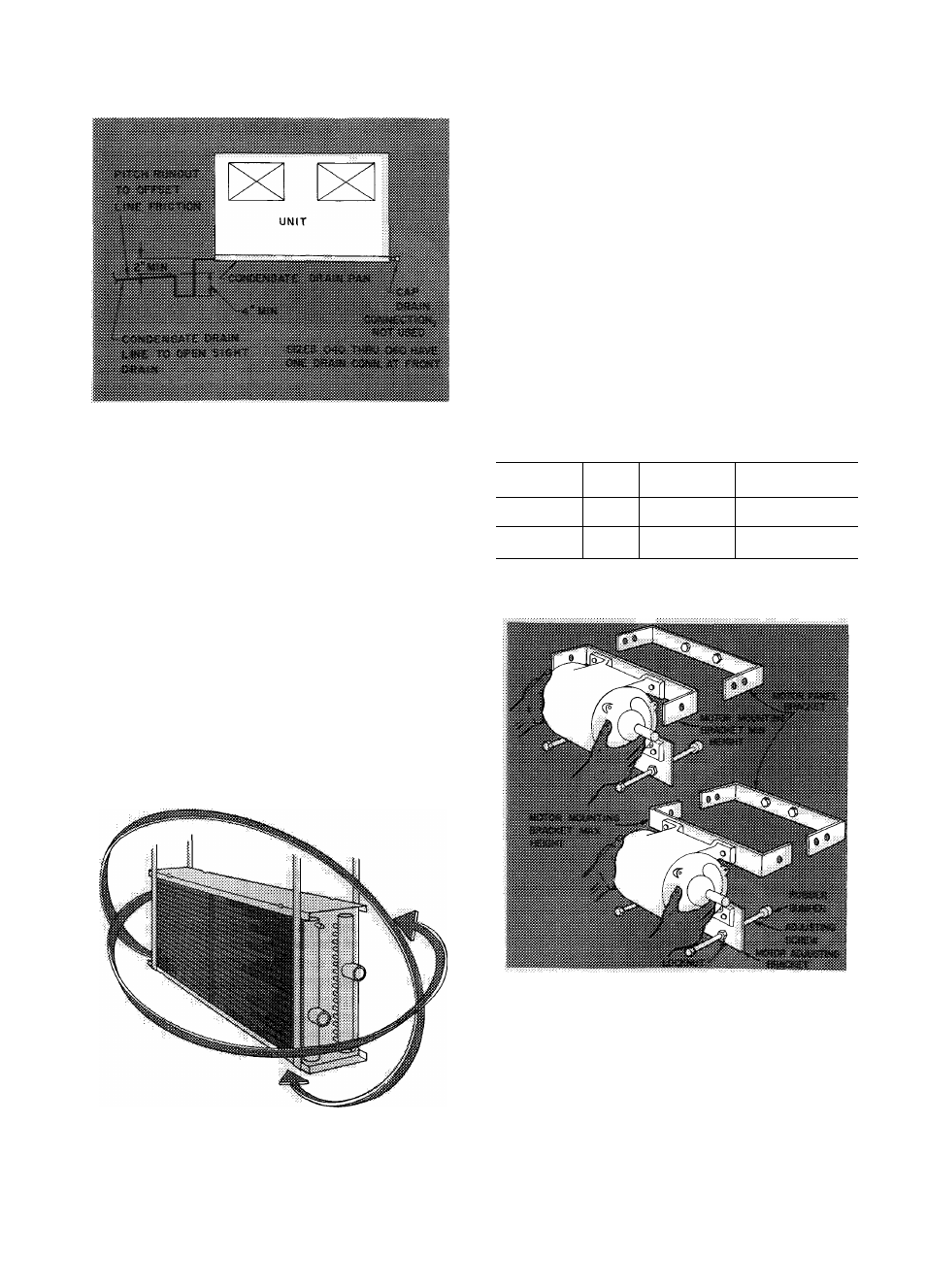
Fig. 19 — Cooling Coil Condensate Piping
Coil Removal and Reversing
1. Remove coil coverplate.
2. Remove air baffle from both ends of coil on
leaving air side.
3. Remove coil hold-down bolts from both ends
of coil.
4. Shde coil out of unit. Lift coils from suspension
points at four corners as close to tube sheets as
possible. Never lift from center. Handle cooling
coils with coil face vertical.
5. Reverse coil per Fig. 20.
6. Reverse steps 1 thru 4 to reinstall. Cooling and
hot water heating coils must be reinstalled so
refrigerant or chilled water supply enters on
air-leaving face of coil and returns on air
entering face. Steam heating coils must be
installed with upper connection for supply and
lower for return. Supply connection has a
raised letter “S” on return-bend type steam
coils. Supply connection is larger than return
on nonfreeze type steam coils.
Fig. 20 — Coil Reversing
Duct Connections
— Make connections per
accepted design practices. Refer to Carrier System
Design Manual for details.
Motor and Drive
GENERAL
1. Excessive tipping will cause oil loss in sleeve
bearing motors. Follow motor manufacturer’s
recommendations.
2. Check job prints to determine correct motor
mounting position.
3. Drive package numbers are marked on drive
package and label on drive end of fan section.
4.
Required center-to-center distance (C/D) be
tween fan and motor shafts is marked on fan
drive package.
5. Refer to Table 7 for motor base used on unit
sizes 070 thru 140. A single bracket is used
universally for unit sizes 040 thru 060. Motors
larger than 50 hp must not be mounted on unit.
Use field-provided, floor-mounted base under
unit and motor.
Table 7 — Motor Base Usage
(Unit Sizes 070 thru 140)
MTR BASE
PART NO.
HP
RANGE*
NEMA FRAME
SIZE RANGE
MOTOR BASE
CRADLE DIM. (in.)
39BA070-453
V
2
-
2
O
56-256T or
56-286U
16 Vs
X
20 V
4
39B A110-453
25-50
284T-326T or
324U-356U
23 V
4
X 26V
‘Corresponds to frame sizes for open dripproof 1750 rpm motors
only.
UNIT SIZES 040 THRU 060 - Refer to Fig. 21.
Fig. 21 — Motor Base (Unit Sizes 040 Thru 060)
1
2
.
Set motor mounting bracket position (min or
max) to provide required drive center-to-center
distance.
Install motor on motor mounting and adjusting
brackets with hardware from accessory drive
package.
3. Install adjusting screw, locknuts, and rubber
bumpers (shipped in cloth bag, taped to motor
base) on motor adjusting bracket. Save three
1 ¡4-20
X
1 ¡2-in. self-tapping screws for belt
guard installation.
19