Carrier 39B User Manual
Page 6
Attention! The text in this document has been recognized automatically. To view the original document, you can use the "Original mode".
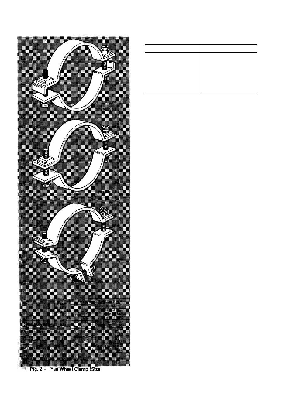
Table 4 — Setscrew Torques
SETSCREW SIZE
TORQUE
10
22 5- 30.5 in.-lb
1/4
52.7- 71 3 in.-lb
5/16
103.7-140.3 in.-lb
3/8
168.3-227.7 in.-lb
7/16
22.1- 29 9 ft-lb
1/2
32 3- 43 7 ft-lb
5/8
78.2-105.8 ft-lb
3/4
107.9-146.1 ft-lb
INSTALLATION
General
DO NOT
1. Remove protective caps from coil piping con
nections until ready to connect piping.
2. Bend or mutilate coil fins.
3. Remove protective cover or grease from fan
shaft until ready to install sheave.
4. Lift by fan shaft extension or coil connections.
5. Remove fan drive from boxes until ready to
install, to prevent loss of parts and installation
information labeled on boxes.
6. Lift face and bypass damper assembly without
providing support under center of assembly.
076-140)
DO
1. Use spacer bars per Fig. 1 when rigging to avoid
bending unit flanges.
2. Make piping and duct connections in accord
ance with standard practices. Refer to Carrier
System Design Manual for details.
3. Leave sufficient clearances for:
a. Condensate trap.
b. Removal of fan shaft and coils.
c.
Service of filters, fan motor, bearings,
damper linkage, and damper motors (at least
30 inches).
d. Piping to permit removal of fan guard.
Base Unit Assembly (Fan and Coil Sections)
NOTES:
1. Base unit and accessories on 39BA sizes 040
thru 060 (arrangements A, B, and D) are
shipped completely assembled, except for
accessory
mixing
box
which
is
shipped
separately.
2. More holes may exist than indicated by these
instructions. Use only those which line up.
3.
Fastener package is shipped with each fan
section. Sealing compound is shipped inside
belt guard.
4. Remove any accessories attached to base unit
that are not in their final location per Tables 1,
2, and 3.
5. Unit suspension is simplified by completely
assembling units prior to rigging.
6. Unit sizes 130 thru 140 must be assembled on a
platform for suspended applications.