Carrier 39B User Manual
Page 12
Attention! The text in this document has been recognized automatically. To view the original document, you can use the "Original mode".
5. Fasten flanges 1 thru 5 of face and bypass
damper
section;
preheat
coil
or
spray
humidifier section with bypass as follows:
a. Arrangements A and B — Fasten flange 1 to
matching flange of applicable accessory with
three fasteners per preceding step 3a.
b. Arrangement D — Fasten flange 1 to match
ing flange of fan section or accessory bypass
heat section with three 1 /4-20 x 1 /2-in.
self-tapping screws and matching flange en
gagement holes. Fasten flange 1 to matching
flange of duct extension with three fasteners
per preceding step 3a.
c. Fasten flanges 2 and 3 to matching flanges
of applicable accessory or cooling coil
section with three fasteners per preceding
step 3a.
d. Fasten flanges 4 and 5 to matching flanges
of applicable accessory(ies) and/or coohng
coil section with four (size 070) or five
(sizes 080 thru 120) fasteners per preceding
step 3b.
6. Tighten screws securely.
7. When face and bypass damper section is used
with accessory humidifier, minimum stops may
be required to ensure air flow thru humidifier
at all times. Install stops on damper actuator
linkage as opposed to directly on damper blades
to prevent possible damage.
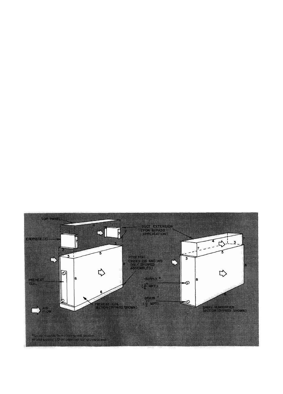
PREHEAT COIL SECTION, AND/OR SPRAY
HUMIDIFIER SECTION WITH AND WITHOUT
BYPASS (Sizes 130 thru 140) - Refer to Fig. 9.
1. Remove shipping crate and apply sealing tape
to flanges on air discharge side of spray
humidifier section only.
2. Remove coil from preheat section to provide
access to internal flanges 5, 6, and 8.
3. Face air discharge side of accessory(ies) toward
air intake side of cooling coil section.
NOTE; Spray humidifier section must be
adjacent to cooling coil section so excess
water can be collected in condensate pan.
Remove factory-installed accessories to do
this and replace same.
4. Duct extension (for accessories with bypass) —
a.
Place one endpiece on each flange 3 of
accessory, with flanges 1 facing each
other.
b.
Line up flanges 2 and 3. Drill one (spray
humidifier section) or two (preheat coil
section) engagement holes in flanges 3
with a no. 3 drill.
c.
Fasten flanges 2 to 3 with one or two
1/4-20 X 1/2-in. self-tapping screws per
two flanges.
d.
Fasten top panel to each flange 1 with two
1/4-20 X 1/2-in. self-tapping screws per
end and both flange 1 engagement holes.
Fig. 9 — Assembly of Accessory Preheat Coil Section and/or Spray Humidifier Section
with and without Bypass (Sizes 130-140)
12