Belt guard, Start-up – Carrier 39B User Manual
Page 22
Attention! The text in this document has been recognized automatically. To view the original document, you can use the "Original mode".
Belt Guard
UNIT SIZES 040 THRU 120
1. Position belt guard and drill three engagement
holes (sizes 040 thru 060) with a no. 5 drill or
four engagement holes (sizes 070 thru 120)
with a no. 3 drill in side of fan section using
mounting bracket clearance holes as templates.
2. Secure guard to fan section with three
1/4-20
X
1/2-in. self-tapping screws.
UNIT SIZES 130 THRU 140
1. Position belt guard and drill eight engagement
holes with a no. 3 drill in side of fan sectit i,
using mounting bracket clearance holes a:
templates.
2. Secure guard to fan section with eight
1/4-20 X 1/2-in. self-tapping screws.
3.
Position two unattached mounting brackets
over unit front or top structural member and
secure to guard with four 1/4-20 x 1/2-in.
self-tapping screws and guard engagement holes.
4. Drill four engagement holes in unit structural
members with a no. 2 drill, using mounting
bracket clearance holes as templates.
5. Secure two mounting brackets to unit struc
tural members with four 1/4-20 x 1/2-in. self
tapping screws.
START-UP
Check List
1. Make certain all construction debris is removed
from unit interior.
2. Check lubrication of fan and motor bearings.
a. Note that bearings are shipped completely
full of grease for corrosion protection and
may run warm temporarily on start-up until
the excess grease has discharged. As a
precaution, cycle unit on and off at one-
minute intervals for five minutes.
b. Sleeve bearing motors are normally shipped
with oil reservoir drained. Fill reservoir
before starting motor.
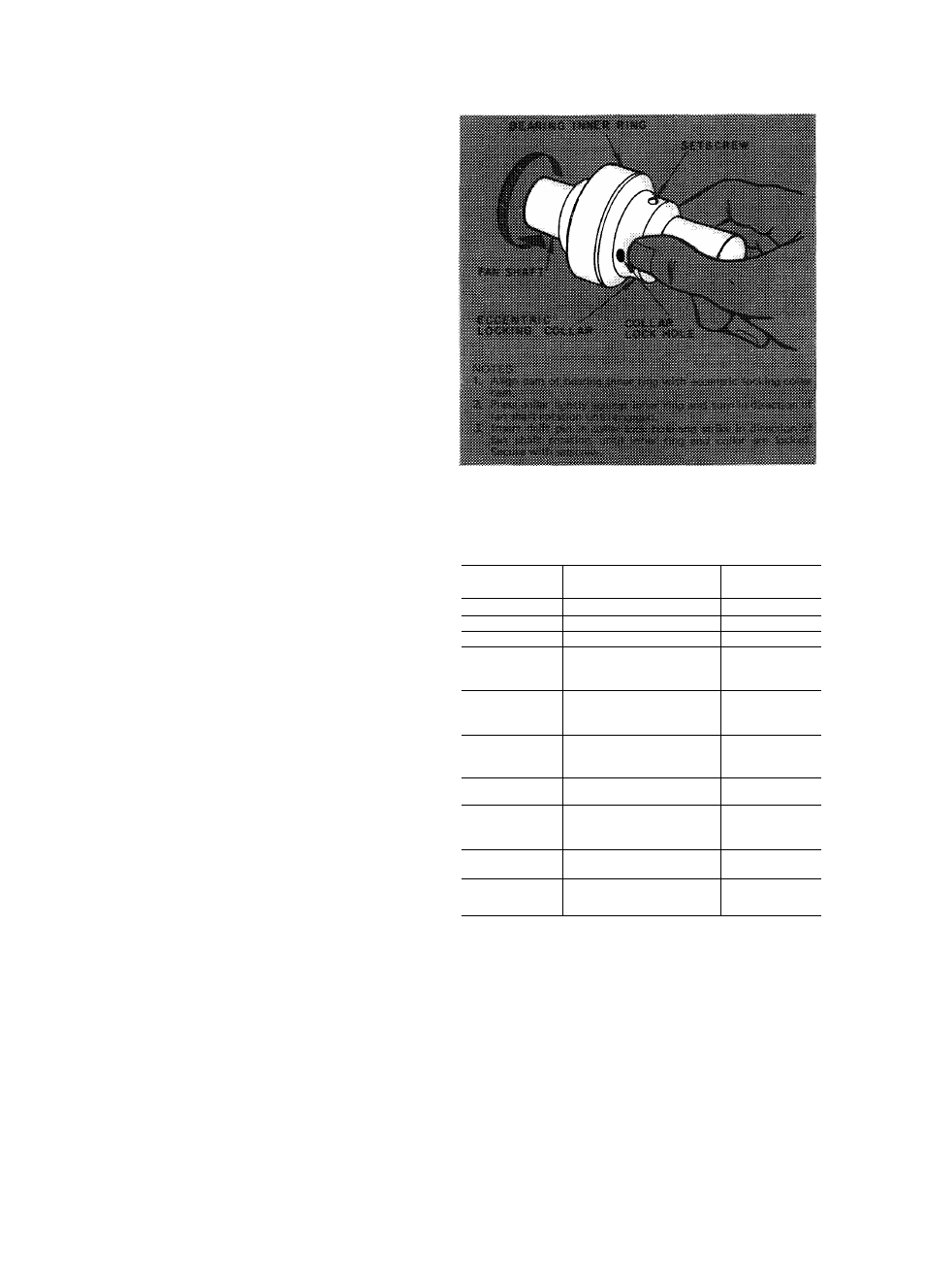
3. Check secureness of bearing locking collars per
Table 4. Refer to Fig. 26 for eccentric type.
Recheck sheave alignment and belt tension.
Make certain fan shaft turns freely and fan
wheels do not rub in housings.
Make certain filters used during building con
struction are replaced with new ones. Refer to
Table 9.
Check direction of rotation and fan speed.
Arrow on fan drive side indicates correct
direction of rotation. Excessive fan speed may
result in condensate carry-over from coohng
cod and/or fan motor overload. Refer to
39B, 39C Operation and Maintenance Instruc
tions for operating Umits.
4.
5.
6
.
7.
Fig. 26 — Securing the Bearing Eccentric
Locking Collar
Table 9 — 39B Filters, 2 Inches Thick,
(No.... Size)
UNIT 39B
LOW VELOCITY AND
MIXING BOX
HIGH
VELOCITY
040
2...16x16
1...16x20
050
2...16x2U
1... 20x25
060
2...20x25
2...16x25
070
2..
. 20x20
2.. . 20x25
2
..16x20
3...25x20
080
ЗИ7Ж20
3
.20x25
3...16x20
6...
16x20
090
'6...2Ux2U
3.. .20x25
3.. .16x20
8...16x20
100
97720x25
3 ..16x20
8
...20x20
105
and
no
3...2D72D~
6
..20x25
9 .16x20
14 .16x20
120
4 ..16x25
14 . 16x25
130
135 and 140
36 ..20x20
36...20x25
24 . 20x20"”"
24 20x25
8. Vibration Check:
NOTE: After final assembly, unit is checked to
ensure vibration level is within tolerance.
If excessive vibration is noted, check following:
Drive alignment
Mismatched belts
Wheel or sheaves loose on shaft
Loose or worn bearings
Loose mounting bolts
Motor out of balance
Sheaves eccentric or out of balance
Vibration isolators improperly adjusted
Worn or corroded wheel (replace if bad)
Accumulation of material on wheel (mate
rial accumulation should he scraped off).
a.
b.
c.
d.
e.
f.
g-
h.
i.
j-
77