Carrier 39B User Manual
Page 10
Attention! The text in this document has been recognized automatically. To view the original document, you can use the "Original mode".
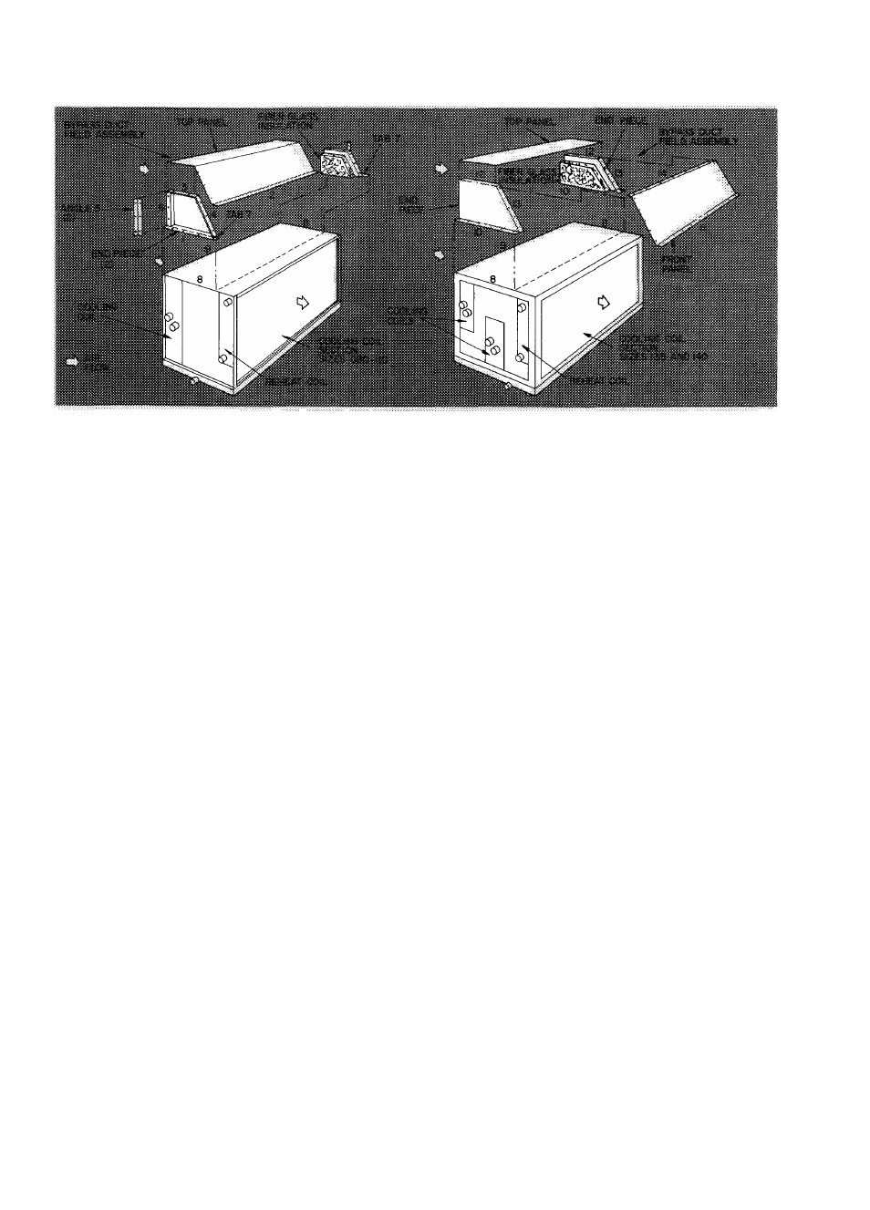
Fig. 7 — Assembly of Accessory Bypass Duct — (Arrangement A Only)
d.
Fasten flange 2 to matching surface of
cooling
coil
section
with
seven
1/4-20 X 1/2-in. self-tapping screws and
matching surface engagement holes.
e. Fasten top panel to each flange 3 and 4 with
two and three 1/4-20 x 1/2-in. self-tapping
screws respectively per end and each
flange 3 and 4 engagement holes.
f.
Fasten one angle 5 to each flange 6 with
three 1/4-20 X 1/2-in. self-tapping screws
and flange 6 engagement holes.
g. Tighten all screws securely.
2. Sizes 135 and 140—
a.
Place one endpiece on one flange 8 of
cooling coil section with fiber glass insulated
side facing second flange 8.
b. Fasten flange 10 to 8 as follows;
(1) Line up flange 10 and 8. Ensure air in
take side of bypass duct is flush with
edge of flange 9
(2) Drill six engagement holes in flange 8
with a no. 3 drill.
(3) Fasten flange 10 to 8 with six
1/4-20 X 1/2-in. self-tapping screws.
c. Loosely fasten one end of top panel to flange
12 with nine 1/4-20
X
1/2-in. self-tapping
screws and flange 12 engagement holes.
d. Place second endpiece on second flange 8 of
cooling coil section with fiber glass insulated
side facing first endpiece.
e. Loosely fasten remaining end of top panel
with nine 1/4-20 X 1/2-in. self-tapping
screws and flange 12 engagement holes.
f.
Loosely fasten front panel to flanges 13
with five 1 /4-20 x 1 /2-in. self-tapping screws
per end and flange 13 engagement holes.
g. Loosely fasten flange 14 to matching edge
of top panel with seven 1/4-20 x 1/2-in.
self-tapping screws and engagement holes
along top panel edge.
h.
Fasten flange 10 of second endpiece as
follows:
(1) Line up flange 10 and 8. Ensure air
intake side of bypass duct is flush with
edge of flange 9.
(2) Drill six engagement holes in flange 8
with a no. 3 drill.
(3) Fasten flange 10 to 8 with six
1/4-20 X 1/2-in. self-tapping screws.
i.
Fasten flange 11 to matching surface of
cooling coil section as follows:
(1) Line up flange 11 and matching surface.
(2) Drill ten engagement holes in matching
surface with a no. 2 drill.
(3) Fasten flange 11 to matching surface
with ten 1/4-20
X
1/2-in. self-tapping
screws.
j. Tighten aU screws securely.
FACE AND BYPASS DAMPER SECTION; PRE
HEAT
COIL
SECTION
AND/OR
SPRAY
HUMIDIFIER SECTION WITH AND WITHOUT
BYPASS (Sizes 070 thru 120) - Refer to Fig. 8.
1. Remove shipping crate(s) and apply sealing tape
to flanges on air discharge side of spray
humidifier section only.
2. Face air discharge side of accessory(ies) toward
air intake side of cooling coil section.
NOTE; Spray humidifier section must be
adjacent to cooling coil section so excess
water can be collected in condensate pan.
Remove factory-installed accessories to do
this and replace same.
10