Carrier 39B User Manual
Page 13
Attention! The text in this document has been recognized automatically. To view the original document, you can use the "Original mode".
5. Fasten flange 4 to matching flange of applicable
accessory (except bypass heat section arranged
for bypass cooling only) with seven 1/4-20
X
1/2-in. self-tapping screws and locknuts.
6. Fasten flange 4 to matching flange of bypass
heat section arranged for bypass coohng only
as follows:
a.
Line up flange 4 with matching flange of
accessory.
b. Drill seven engagement holes in matching
flange with a no. 3 drill.
c. Fasten flange 4 to matching flange with
seven 1/4-20 x 1/2-in. self-tapping screws.
7. Fasten flange 5 to matching flange of appli
cable accessory or cooHng coil section with
seven 3/8-16 x 3/4-in. hex head cap screws and
matching flange weld nuts.
8. Fasten flange 6 to matching flange of applicable
accessory with seven 3/8-16 x 3/4-in. hex head
cap screws and matching flange weld nuts.
9. Fasten flange 6 to matching flange of coohng
coil section with seven 1/4-20 x 1/2-in. self
tapping screws and matching flange engage
ment holes.
10. Fasten flanges 7 to matching flanges of appli
cable accessory with two 1/4-20 x 1/2-in. self
tapping screws per two flanges and matching
flange engagement holes (bypass duct) or lock
nuts (duct extension or bypass heat section).
11. Fasten flanges 8 to matching flanges of appli
cable accessory or coohng coil section with
five 3/8-16
X
3/4-in. hex head cap screws and
hex nuts per two flanges.
12. Tighten all screws securely.
13. Replace coil in preheat section.
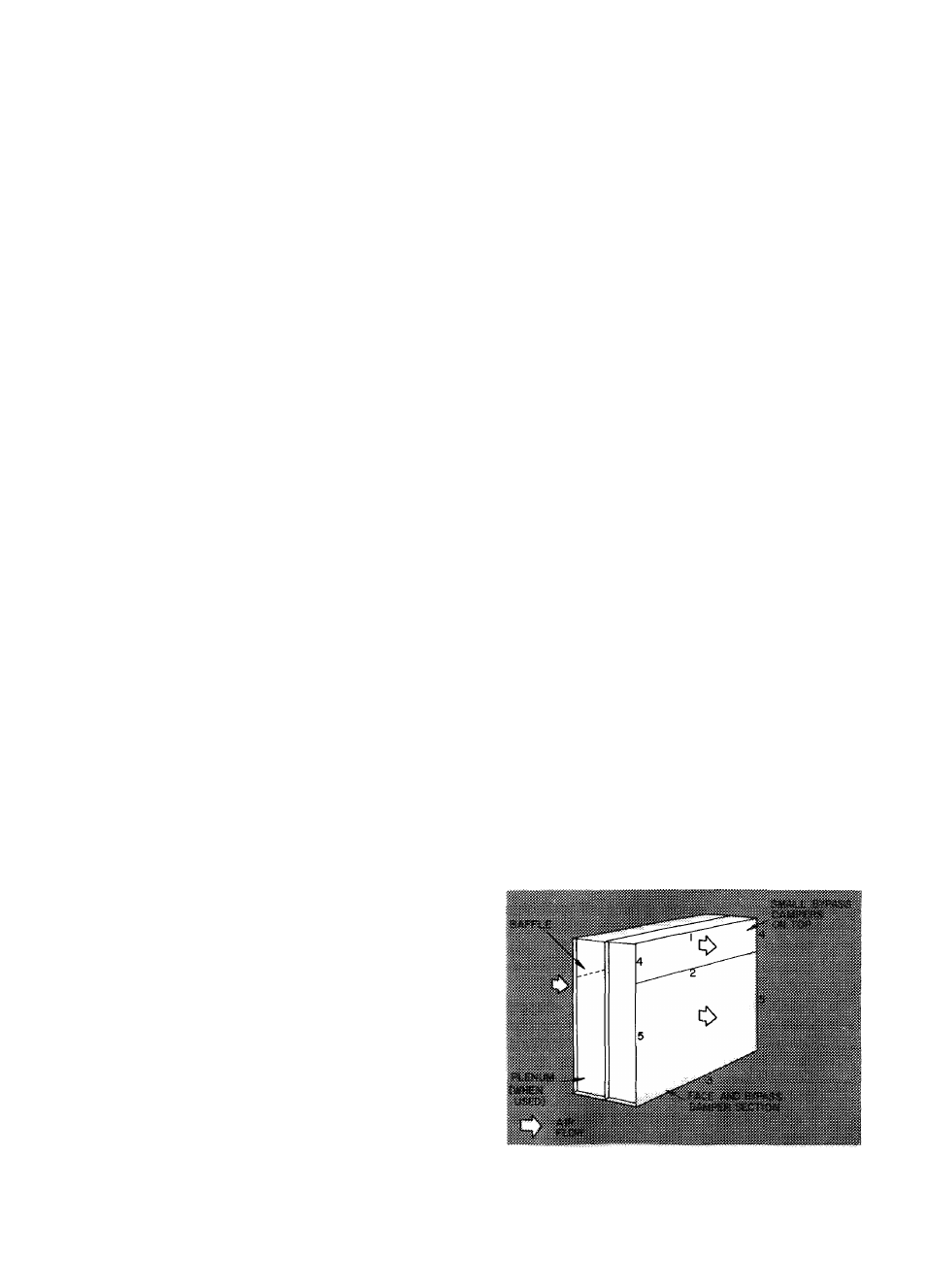
FACE
AND
BYPASS
DAMPER
SECTION
(Size 130 thru 140) - Refer to Eig. 10.
1. FoUow preceding steps 1 and 3.
2. Fasten flange 1 to matching flange of apphcable
accessory (except bypass heat section arranged
for bypass cooling only) with seven 1/4-20
X
1/2-in. self-tapping screws and locknuts.
3. Fasten flange 1 to matching flange of bypass
heat section arranged for bypass coohng only
as follows:
a. Line up flange 1 with matching flange of
accessory bypass heat section.
b. Drill seven engagement holes in matching
flange with a no. 3 drill.
c. Fasten flange 1 to matching flange with
seven 1/4-20 x 1/2-in. self-tapping screws.
4. Fasten flange 2 to matching flange of apph
cable accessory or coohng coil section (preheat
coil section; sizes 135 and 140 excluded) with
seven 3/8-16 x 1-in. hex head cap screws per
flange and matching flange weld nuts.
5. Fasten flange 2 to matching flange of preheat
coil section (sizes 135 and 140) as follows:
a.
Line up flange 2 with matching flange of
preheat coil section.
b. Follow preceding steps 3b and 3c (sub
stitute flange 2 for flange 1 in step 3 c).
6. Fasten flange 3 to matching flange of apphcable
accessory or coohng coil section (preheat coil
and cooling coil sections, sizes 135 and 140
excluded) with seven 3/8-16 x 1-in. hex head
cap screws and matching flange weld nuts.
7. Fasten flange 3 to matching flange of preheat
coil section (sizes 135 and 140) with seven
3/8-16 X 1-in. hex head cap screws and hex nuts.
8. Fasten flange 3 to matching flange of coohng
coil section (sizes 135 and 140) with seven
1/4-20 X 1/2-in. self-tapping screws and match
ing flange engagement holes.
9. Fasten flanges 4 to matching flanges of apph
cable accessory (bypass duct excluded) with
two 1/4-20 X 1/2-in. self-tapping screws and
locknuts per flange.
10. Fasten flange 4 to matching flanges of accessory
bypass duct with two 1/4-20 x 1/2-in. self
tapping screws and matching flange engagement
holes.
11. Fasten flanges 5 to matching flanges of apph
cable accessory or coohng coil section with:
five (accessory or coohng coil section —
size
130);
five
(accessory
section
—
sizes 135 and 140); six (coohng coil section —
sizes 135 and 140) 3/8-16 x 1-in. hex head cap
screws and hex nuts per two flanges.
12. Tighten all screws securely.
13. When face and bypass damper section is used
with accessory humidifier, minimum stops
may be required to ensure air flow thru
humidifier at all times. Install stops on damper
actuator hnkage as opposed to directly on
damper blades to prevent possible damage.
Fig. 10 — Assembly of Accessory Face and Bypass
Damper Section — (Sizes 130-140)
13